|
|
|
PDF WEDPN4M64V Data sheet ( Hoja de datos )
| Número de pieza | WEDPN4M64V | |
| Descripción | 4M x 64 SDRAM | |
| Fabricantes | White Electronic Designs | |
| Logotipo | ||
Hay una vista previa y un enlace de descarga de WEDPN4M64V (archivo pdf) en la parte inferior de esta página. Total 12 Páginas | ||
|
No Preview Available !
White Electronic Designs
WEDPN4M64V-XBX
4Mx64 Synchronous DRAM
FEATURES
GENERAL DESCRIPTION
High Frequency = 100, 125, 133MHz
Package:
• 219 Plastic Ball Grid Array (PBGA), 21 x 21mm
Single 3.3V ±0.3V power supply
Fully Synchronous; all signals registered on positive
edge of system clock cycle
Internal pipelined operation; column address can be
changed every clock cycle
Internal banks for hiding row access/precharge
Programmable Burst length 1,2,4,8 or full page
4096 refresh cycles
Commercial, Industrial and Military Temperature
Ranges
Organized as 4M x 64
The 32MByte (256Mb) SDRAM is a high-speed CMOS,
dynamic random-access ,memory using 4 chips containing
67,108,864 bits. Each chip is internally configured as a
quad-bank DRAM with a synchronous interface. Each of the
chip’s 16,777,216-bit banks is organized as 4,096 rows by
256 columns by 16 bits.
Read and write accesses to the SDRAM are burst oriented;
accesses start at a selected location and continue for
a programmed number of locations in a programmed
sequence. Accesses begin with the registration of an ACTIVE
command, which is then followed by a READ or WRITE
command. The address bits registered coincident with the
ACTIVE command are used to select the bank and row to
be accessed (BA0, BA1 select the bank; A0-11 select the
row). The address bits registered coincident with the READ
or WRITE command are used to select the starting column
location for the burst access.
• User Configurable as 2x4Mx32 or 4x4Mx16
The SDRAM provides for programmable READ or WRITE
Weight: WEDPN4M64V-XBX - 2 grams typical
burst lengths of 1, 2, 4 or 8 locations, or the full page, with
a burst terminate option. An AUTO PRECHARGE function
BENEFITS
may be enabled to provide a self-timed row precharge that
is initiated at the end of the burst sequence.
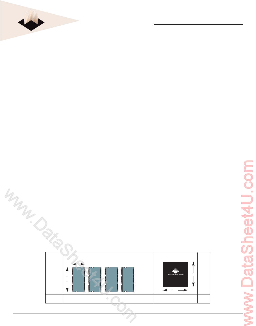
58% SPACE SAVINGS
Reduced part count
w Reduced trace lengths for lower parasitic
w capacitance
wLaminate interposer for optimum TCE match
Suitable for hi-reliability applications
.DUpgradeable to 8M x 64 (contact factory for
availability)
ata*This product is subject to change without notice.
The 256Mb SDRAM uses an internal pipelined architecture to
achieve high-speed operation. This architecture is compatible
with the 2n rule of prefetch architectures, but it also allows
the column address to be changed on every clock cycle to
achieve a high-speed, fully random access. Precharging one
bank while accessing one of the other three banks will hide
the precharge cycles and provide seamless, high-speed,
random-access operation.
The 256Mb SDRAM is designed to operate in 3.3V, low-
power memory systems. An auto refresh mode is provided,
along with a power-saving, power-down mode.
Sh Discrete Approach
11.9
eet54
422.3 TSOP
54
TSOP
54
TSOP
54
TSOP
U.cArea
4 x 265mm2 = 1061mm2
ACTUAL SIZE
WEDPN4M64V-XBX
21
21
S
A
V
I
N
G
S
441mm2 58%
omWhite Electronic Designs Corp. reserves the right to change products or specifications without notice.
January 2005
Rev. 8
1 White Electronic Designs Corporation • (602) 437-1520 • www.wedc.com
1 page 
White Electronic Designs
WEDPN4M64V-XBX
FIGURE 2 – MODE REGISTER DEFINITION
A11 A10 A9 A8 A7 A6 A5 A4 A3 A2 A1 A0 Address Bus
Reserved* WB Op Mode CAS Latency BT Burst Length
Mode Register (Mx)
*Should program
M11, M10 = 0, 0
to ensure compatibility
with future devices.
M2 M1M0
0 00
0 01
0 10
0 11
1 00
1 01
1 10
1 11
Burst Length
M3 = 0
1
2
4
8
Reserved
Reserved
Reserved
Full Page
M3 = 1
1
2
4
8
Reserved
Reserved
Reserved
Reserved
M3
0
1
M6 M5 M4
0 00
0 01
0 10
0 11
1 00
1 01
1 10
1 11
Burst Type
Sequential
Interleaved
CAS Latency
Reserved
Reserved
2
3
Reserved
Reserved
Reserved
Reserved
M8 M7 M6-M0 Operating Mode
0 0 Defined Standard Operation
--
- All other states reserved
M9 Write Burst Mode
0 Programmed Burst Length
1 Single Location Access
TABLE 1 – BURST DEFINITION
Burst
Length
2
4
8
Full
Page
(y)
Starting Column
Address
A0
0
1
A1 A0
00
01
10
11
A2 A1 A0
000
001
010
011
100
101
110
111
n = A0-9/8/7
(location 0-y)
Order of Accesses Within a Burst
Type = Sequential Type = Interleaved
0-1 0-1
1-0 1-0
0-1-2-3
1-2-3-0
2-3-0-1
3-0-1-2
0-1-2-3
1-0-3-2
2-3-0-1
3-2-1-0
0-1-2-3-4-5-6-7
1-2-3-4-5-6-7-0
2-3-4-5-6-7-0-1
3-4-5-6-7-0-1-2
4-5-6-7-0-1-2-3
5-6-7-0-1-2-3-4
6-7-0-1-2-3-4-5
7-0-1-2-3-4-5-6
Cn, Cn + 1, Cn + 2
Cn + 3, Cn + 4...
…Cn - 1,
Cn…
0-1-2-3-4-5-6-7
1-0-3-2-5-4-7-6
2-3-0-1-6-7-4-5
3-2-1-0-7-6-5-4
4-5-6-7-0-1-2-3
5-4-7-6-1-0-3-2
6-7-4-5-2-3-0-1
7-6-5-4-3-2-1-0
Not Supported
NOTES:
1. For full-page accesses: y = 256.
2. For a burst length of two, A1-7 select the block-of-two burst; A0 selects the starting
column within the block.
3. For a burst length of four, A2-7 select the block-of-four burst; A0-1 select the starting
column within the block.
4. For a burst length of eight, A3-7 select the block-of-eight burst; A0-2 select the
starting column within the block.
5. For a full-page burst, the full row is selected and A0-7 select the starting column.
6. Whenever a boundary of the block is reached within a given sequence above, the
following access wraps within the block.
7. For a burst length of one, A0-7 select the unique column to be accessed, and Mode
Register bit M3 is ignored.
White Electronic Designs Corp. reserves the right to change products or specifications without notice.
January 2005
Rev. 8
5 White Electronic Designs Corporation • (602) 437-1520 • www.wedc.com
5 Page 
White Electronic Designs
WEDPN4M64V-XBX
AC FUNCTIONAL CHARACTERISTICS (NOTES 5,6,7,8,9,11)
Parameter/Condition
READ/WRITE command to READ/WRITE command (17)
CKE to clock disable or power-down entry mode (14)
CKE to clock enable or power-down exit setup mode (14)
DQM to input data delay (17)
DQM to data mask during WRITEs (17)
DQM to data high-impedance during READs (17)
WRITE command to input data delay (17)
Data-in to ACTIVE command (15)
Data-in to PRECHARGE command (16)
Last data-in to burst STOP command (17)
Last data-in to new READ/WRITE command (17)
Last data-in to PRECHARGE command (16)
LOAD MODE REGISTER command to ACTIVE or REFRESH command (25)
Data-out to high-impedance from PRECHARGE command (17)
CL = 3
CL = 2
Symbol
tCCD
tCKED
tPED
tDQD
tDQM
tDQZ
tDWD
tDAL
tDPL
tBDL
tCDL
tRDL
tMRD
tROH
tROH
-100
1
1
1
0
0
2
0
4
2
1
1
2
2
3
2
-125
1
1
1
0
0
2
0
5
2
1
1
2
2
3
—
-133
1
1
1
0
0
2
0
5
2
1
1
2
2
3
—
Units
tCK
tCK
tCK
tCK
tCK
tCK
tCK
tCK
tCK
tCK
tCK
tCK
tCK
tCK
tCK
NOTES
1. All voltages referenced to VSS.
2. This parameter is not tested but garanteed by design. f = 1 MHz, TA = 25°C.
3. IDD is dependent on output loading and cycle rates. Specified values are obtained
with minimum cycle time and the outputs open.
4. Enables on-chip refresh and address counters.
5. The minimum specifications are used only to indicate cycle time at which proper
operation over the full temperature range is ensured.
6. An initial pause of 100µs is required after power-up, followed by two AUTO
REFRESH commands, before proper device operation is ensured. (VCC must be
powered up simultaneously.) The two AUTO REFRESH command wake-ups should
be repeated any time the tREF refresh requirement is exceeded.
7. AC characteristics assume tT = 1ns.
8. In addition to meeting the transition rate specification, the clock and CKE must transit
between VIH and VIL (or between VIL and VIH) in a monotonic manner.
9. Outputs measured at 1.5V with equivalent load:
50Ω
Q 1.5V
10. tHZ defines the time at which the output achieves the open circuit condition; it is not a
reference to VOH or VOL. The last valid data element will meet tOH before going High-
Z.
11. AC timing and IDD tests have VIL = 0V and VIH = 3V, with timing referenced to 1.5V
crossover point.
12. Other input signals are allowed to transition no more than once every two clocks and
are otherwise at valid VIH or VIL levels.
13. ICC specifications are tested after the device is properly initialized.
14. Timing actually specified by tCKS; clock(s) specified as a reference only at minimum
cycle rate.
15. Timing actually specified by tWR plus tRP; clock(s) specified as a reference only at
minimum cycle rate.
16. Timing actually specified by tWR.
17. Required clocks are specified by JEDEC functionality and are not dependent on any
timing parameter.
18. The ICC current will decrease as the CAS latency is reduced. This is due to the fact
that the maximum cycle rate is slower as the CAS latency is reduced.
19. Address transitions average one transition every two clocks.
20. CK must be toggled a minimum of two times during this period.
21. VIH overshoot: VIH (MAX) = VCC + 2V for a pulse width - 3ns, and the pulse width
cannot be greater than one third of the cycle rate. VIL undershoot: VIL (MIN) = -2V for
a pulse width - 3ns.
22. The clock frequency must remain constant (stable clock is defined as a signal cycling
within timing constraints specified for the clock pin) during access or precharge states
(READ, WRITE, including tWR, and PRECHARGE commands). CKE may be used to
reduce the data rate.
23. Auto precharge mode only. The precharge timing budget (tRP) begins 7.5ns/7ns after
the first clock delay, after the last WRITE is executed.
24. Precharge mode only.
25. JEDEC and PC100 specify three clocks.
26. Parameter guaranteed by design.
27. Self refresh available in commercial and industrial temperatures only.
White Electronic Designs Corp. reserves the right to change products or specifications without notice.
January 2005
Rev. 8
11 White Electronic Designs Corporation • (602) 437-1520 • www.wedc.com
11 Page | ||
| Páginas | Total 12 Páginas | |
| PDF Descargar | [ Datasheet WEDPN4M64V.PDF ] | |
Hoja de datos destacado
| Número de pieza | Descripción | Fabricantes |
| WEDPN4M64V | 4M x 64 SDRAM | White Electronic Designs |
| Número de pieza | Descripción | Fabricantes |
| SLA6805M | High Voltage 3 phase Motor Driver IC. |
Sanken |
| SDC1742 | 12- and 14-Bit Hybrid Synchro / Resolver-to-Digital Converters. |
Analog Devices |
|
DataSheet.es es una pagina web que funciona como un repositorio de manuales o hoja de datos de muchos de los productos más populares, |
| DataSheet.es | 2020 | Privacy Policy | Contacto | Buscar |