|
|
|
PDF KK2411N Data sheet ( Hoja de datos )
| Número de pieza | KK2411N | |
| Descripción | Tone Ringer | |
| Fabricantes | Kodenshi | |
| Logotipo | ||
Hay una vista previa y un enlace de descarga de KK2411N (archivo pdf) en la parte inferior de esta página. Total 6 Páginas | ||
|
No Preview Available !
TECHNICAL DATA
Tone Ringer
KK2411N/D
The KK2411 is a bipolar integrated circuit designed for telephone
bell replacement.
• Designed for Telephone Bell Replacement
• Low Current Drain
• Adjustable 2-frequency Tone
• Adjustable Warbling Rate
• Extension Tone Ringer Modules
• Alarms or Other Alerting Devices
• Adjustable for Reduced Supply Initiation Current.
• Built-in hysteresis prevents false triggering and rotary dial
‘Chirps’
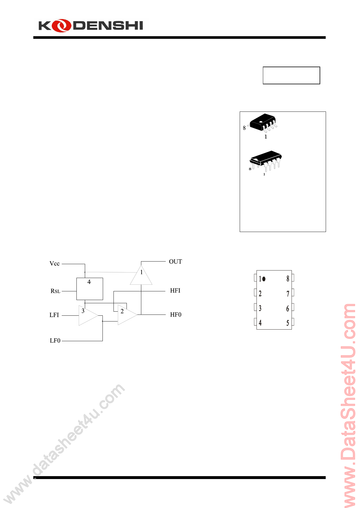
8-SOP
8-DIP
TA = -45° to 65° C
LOGIC DIAGRAM
PIN 1 = VCC
PIN 5 = GND
1. Output amplifier
2. High frequency oscillator
3. Low frequency oscillator
4. Hysteresis regulator
om(Regulator circuit has built-in hysteresis to
www.datasheet4u.cprevent false triggering and rotary dial “Chirps”)
PIN ASSIGNMENT
V CC OUT
R SL HFI
LFI HF0
LF0 GND
1
1 page 
APPLICATION CIRCUIT
KK3726A
igure 3
F
APPLICATION NOTE
The application circuit illustrates the use of the KK2411 devices in typical telephone or extension tone ringer application.
The AC ringer signal voltage appears across the TIP and RING inputs of the circuit and is attenuated by capacitor C1
and resistor R1.
C1 also provides isolation from DC voltages (48V) on the exchange line.
After full wave rectification by the bridge diode, the waveform is filtered by capacitor C4 to provide a DC supply for
the tone ringer chip.
As this voltage exceeds the initiation voltage (VSI), oscillation starts.
With the components shown, the ouptut frequency chops between 512(fh1) and 640Hz(fh2) at a 10Hz(fL) rate.
The loudspeaker load is coupled through a 1300Ω to 8Ω transformer.
The output coupling capacitor C5 is required with transformer coupled loads.
When driving a piezo-ceramic transducer type load, the coupling C5 and transformer (1300Ω:8Ω) are not required.
However, a current limiting resistor is required.
The low frequency oscillator oscillates at a rate (fL) controlled by an external resistor (R2) and capacitor (C2).
The frequency can be determined using the relation fL=1/1.289R2*C2. The high frequency oscillates at a fH1, fH2
controlled by an external resistor (R3) and capacitor (C3). The frequency can be determined using the relation
fH1=1/1.504R3*C3, fH2=1/1.203R3*C3.
Pin 2 allows connection of an external resistor RSL, which is used to program the solpe of the supply current vs supply
voltage characteristics (see Fig2), and hence the supply current up to the initiation voltage ( VSI ). This initiation voltage
remains constant independent of RSL.
The supply current drawn prior to triggering varies inversely with RSL, decreasing for increasing value of resistance.
Thus, increasing the value of RSL will decrease the amount of AC ringing current required to trigger the device. As such,
longer sucribser loops are possible since less voltage is dropped per unit length of loop wire due to the lower current
level. RSL can also be used to compensated for smaller AC couplin capacitors (C5 on Fig 3) (higher impedance) to the
line which can be used to alter the ringer equivalence number of a tone ringer circuit.
The graph in Fig2 illustrates the variation of supply current with supply voltage. Three curves are drawn to show the
variation of initiation current with RSL. Curve B( RSL=6.8KΩ) shows the I-V characteristic for the KK2411 tone ringer.
Curve A is a plot with RSL<6.8KΩ and shows an increase in the current drawn up to the initiation voltageVSI. The I-V
characteristic after initiation remains unchanged. Curve C illustrates the effect of increasing RSL above 6.8KΩ initiation
current decreases but again current after triggering is unchanged.
5
5 Page | ||
| Páginas | Total 6 Páginas | |
| PDF Descargar | [ Datasheet KK2411N.PDF ] | |
Hoja de datos destacado
| Número de pieza | Descripción | Fabricantes |
| KK2411D | Tone Ringer | Kodenshi |
| KK2411N | Tone Ringer | Kodenshi |
| Número de pieza | Descripción | Fabricantes |
| SLA6805M | High Voltage 3 phase Motor Driver IC. |
Sanken |
| SDC1742 | 12- and 14-Bit Hybrid Synchro / Resolver-to-Digital Converters. |
Analog Devices |
|
DataSheet.es es una pagina web que funciona como un repositorio de manuales o hoja de datos de muchos de los productos más populares, |
| DataSheet.es | 2020 | Privacy Policy | Contacto | Buscar |