|
|
|
PDF DRV102 Data sheet ( Hoja de datos )
| Número de pieza | DRV102 | |
| Descripción | PWM SOLENOID/VALVE DRIVER | |
| Fabricantes | Burr-Brown Corporation | |
| Logotipo | ||
Hay una vista previa y un enlace de descarga de DRV102 (archivo pdf) en la parte inferior de esta página. Total 19 Páginas | ||
|
No Preview Available !
®
DRV102
DRV102
DRV102
For most current data sheet and other product
information, visit www.burr-brown.com
PWM SOLENOID/VALVE DRIVER
FEATURES
q HIGH OUTPUT DRIVE: 2.7A
q WIDE SUPPLY RANGE: +8V to +60V
q COMPLETE FUNCTION
PWM Output
Internal 24kHz Oscillator
Digital Control Input
Adjustable Delay and Duty Cycle
Over/ Under Current Indicator
q FULLY PROTECTED
Thermal Shutdown with Indicator
Internal Current Limit
q POWER PACKAGES: 7-Lead TO-220 and
7-Lead Surface-Mount DDPAK
APPLICATIONS
q ELECTROMECHANICAL DRIVER:
Solenoids Positioners
Actuators High Power Relays/Contactors
Valves
Clutches/Brakes
q SOLENOID OVERHEAT PROTECTORS
q FLUID AND GAS FLOW CONTROLLERS
q PART HANDLERS
q ELECTRICAL HEATERS/COOLERS
q MOTOR SPEED CONTROLLERS
q INDUSTRIAL CONTROL
q FACTORY AUTOMATION
q MEDICAL ANALYSIS
q PHOTOGRAPHIC PROCESSING
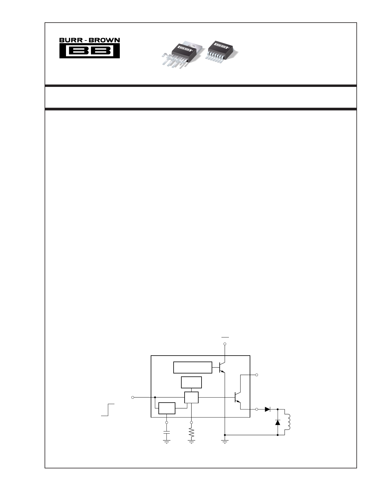
DESCRIPTION
The DRV102 is a high-side power switch employing
a pulse-width modulated (PWM) output. Its rugged
design is optimized for driving electromechanical de-
vices such as valves, solenoids, relays, actuators, and
positioners. The DRV102 is also ideal for driving
thermal devices such as heaters and lamps. PWM
operation conserves power and reduces heat rise in the
device, resulting in higher reliability. In addition, ad-
justable PWM allows fine control of the power deliv-
ered to the load. Time from dc output to PWM output
is externally adjustable.
The DRV102 can be set to provide a strong initial
closure, automatically switching to a “soft” hold mode
for power savings. Duty cycle can be controlled by a
resistor, analog voltage, or digital-to-analog converter
for versatility. A flag output indicates thermal shut-
down and over/under current limit. A wide supply
range allows use with a variety of actuators.
The DRV102 is available in 7-lead staggered TO-220
package and a 7-lead surface-mount DDPAK plastic
power package. It operates from –55°C to +125°C.
Flag
Input 1
On (TTL-Compatible)
Off
Thermal Shutdown
Over/Under Current
24kHz
Oscillator
7
DRV102
5
(+8V to +60V)
VS
PWM
Delay
2
3 Gnd(1) 4
6
Out
Delay
Adjust
Duty Cycle
Adjust
(Gnd electrically
connected to tab)
Load
International Airport Industrial Park • Mailing Address: PO Box 11400, Tucson, AZ 85734 • Street Address: 6730 S. Tucson Blvd., Tucson, AZ 85706 • Tel: (520) 746-1111
Twx: 910-952-1111 • Internet: http://www.burr-brown.com/ • Cable: BBRCORP • Telex: 066-6491 • FAX: (520) 889-1510 • Immediate Product Info: (800) 548-6132
©1998 Burr-Brown Corporation
PDS-1471B
Printed in U.S.A. March, 1999
1 page 
TYPICAL PERFORMANCE CURVES
At TC = +25°C and VS = +24V, unless otherwise noted.
DUTY CYCLE and DUTY CYCLE ERROR vs VOLTAGE
90 8
80
Duty Cycle
6
70 IO = 0.1A 4
60
Error
2
50 0
40 –2
IO = 1A
30 –4
IO = 0.1A to 1A
20 –6
10
0
–8
0.5 1.0 1.5 2.0 2.5 3.0 3.5 4.0
VPWM (V)
DUTY CYCLE vs TEMPERATURE
54
RPWM = 25.5kΩ
53
VS = +8V
52
51 VS = +24V
50
49
48
–75
–50 –25
VS = +60V
0 25 50
Temperature (°C)
75 100 125
OUTPUT SATURATION VOLTAGE vs TEMPERATURE
2.25
2
1.75
1.5
IO = 2A
IO = 1.5A
IO = 1A
1.25
1
IO = 0.1A
0.75
–75
–50 –25
0 25 50
Temperature (°C)
75 100 125
3.25
CURRENT LIMIT vs TEMPERATURE
VS = +8V, Load = 1Ω
3
2.75 VS = +60V, Load = 5Ω
2.5
VS = +24V, Load = 5Ω
2.25
2
–75
–50 –25
0 25 50
Temperature (°C)
75 100 125
QUIESCENT CURRENT vs TEMPERATURE
8
7.5
VS = +60V
7
6.5 VS = +24V
6
VS = +8V
5.5
–75 –50 –25
0
25 50
Temperature (°C)
75 100 125
UNDER-SCALE CURRENT vs TEMPERATURE
20
VS = +8V to +60V
18
16
14
12
10
–75 –50 –25 0 25 50
Temperature (°C)
75 100 125
®
5 DRV102
5 Page 
STATUS FLAG
Flag (pin 7) provides fault indication for under-current,
over-current, and thermal shutdown conditions. During a
fault condition, Flag output is driven low (pin voltage
typically drops to 0.2V). A pull-up resistor, as shown in
Figure 7, is required to interface with standard logic. A small
value capacitor may be needed between Flag and ground in
noisy applications.
Figure 7 gives an example of a non-latching fault monitoring
circuit, while Figure 8 provides a latching version. The Flag
pin can sink several milliamps, sufficient to drive external
logic circuitry or an LED (Figure 9) to indicate when a fault
has occurred. In addition, the Flag pin can be used to turn off
other DRV102’s in a system for chain fault protection.
+5V
+5V
5kΩ
Flag 7
Thermal Shutdown
Over/Under Current
(LED)
HLMP-Q156
5
VS
DRV102
Gnd 4
6
Out
5kΩ
Pull-Up
TTL or HCT
Flag 7
Thermal Shutdown
Over/Under Current
5
VS
DRV102
Gnd 4
6
Out
FIGURE 7. Non-Latching Fault Monitoring Circuit.
Flag
Flag
Flag Reset
74XX76A
VS
QJ
Q
CLR CLK
GND K
+5V
20kΩ
(1)
Flag 7
Thermal Shutdown
Over/Under Current
DRV102
Gnd 4
5
VS
6
Out
FIGURE 9. LED to Indicate Fault Condition.
Over/Under Current Fault
An over-current fault occurs when the output current ex-
ceeds the current limit. All units are guaranteed to drive 2A
without current limiting. Typically, units will limit at 2.7A.
The status flag is not latched. Since current during PWM
mode is switched on and off, the flag output will be modu-
lated with PWM timing (see flag waveforms in the Typical
Performance Curves).
An under-current fault occurs when the output current is
below the under-scale current threshold (typically 16mA).
For example, this function indicates when the load is discon-
nected. Again, the flag output is not latched, so an under-
current condition during PWM mode will produce a flag
output that is modulated by the PWM waveform. An initial,
brief under-current flag normally appears driving inductive
loads and may be avoided by adding a parallel resistor
sufficient to move the initial current above the under-current
threshold. Avoid adding capacitance to pin 6 (Out) as it may
cause momentary current limiting.
Over-Temperature Fault
A thermal fault occurs when the die reaches approximately
165°C, producing a similar effect as pulling the input low.
Internal shutdown circuitry disables the output and resets the
Delay Adjust pin. The Flag is latched in the low state (fault
condition) until the die has cooled to approximately 150°C.
A thermal fault can occur in any mode of operation. Recov-
ery from thermal fault will start in delay mode (constant dc
output).
NOTE: (1) Small capacitor (10pF) may be required in noisy environments.
FIGURE 8. Latching Fault Monitoring Circuit.
11
DRV102
®
11 Page | ||
| Páginas | Total 19 Páginas | |
| PDF Descargar | [ Datasheet DRV102.PDF ] | |
Hoja de datos destacado
| Número de pieza | Descripción | Fabricantes |
| DRV101 | PWM SOLENOID/VALVE DRIVER | Burr-Brown Corporation |
| DRV101 | PWM Solenoid/Valve Driver (Rev. B) | Texas Instruments |
| DRV102 | PWM SOLENOID/VALVE DRIVER | Burr-Brown Corporation |
| DRV102 | PWM Solenoid/Valve Driver (Rev. B) | Texas Instruments |
| Número de pieza | Descripción | Fabricantes |
| SLA6805M | High Voltage 3 phase Motor Driver IC. |
Sanken |
| SDC1742 | 12- and 14-Bit Hybrid Synchro / Resolver-to-Digital Converters. |
Analog Devices |
|
DataSheet.es es una pagina web que funciona como un repositorio de manuales o hoja de datos de muchos de los productos más populares, |
| DataSheet.es | 2020 | Privacy Policy | Contacto | Buscar |