|
|
|
PDF WM8608 Data sheet ( Hoja de datos )
| Número de pieza | WM8608 | |
| Descripción | 5 TO 7.1 CHANNEL PWM CONTROLLER | |
| Fabricantes | Wolfson Microelectronics | |
| Logotipo | ||
Hay una vista previa y un enlace de descarga de WM8608 (archivo pdf) en la parte inferior de esta página. Total 30 Páginas | ||
|
No Preview Available !
w
WM8608
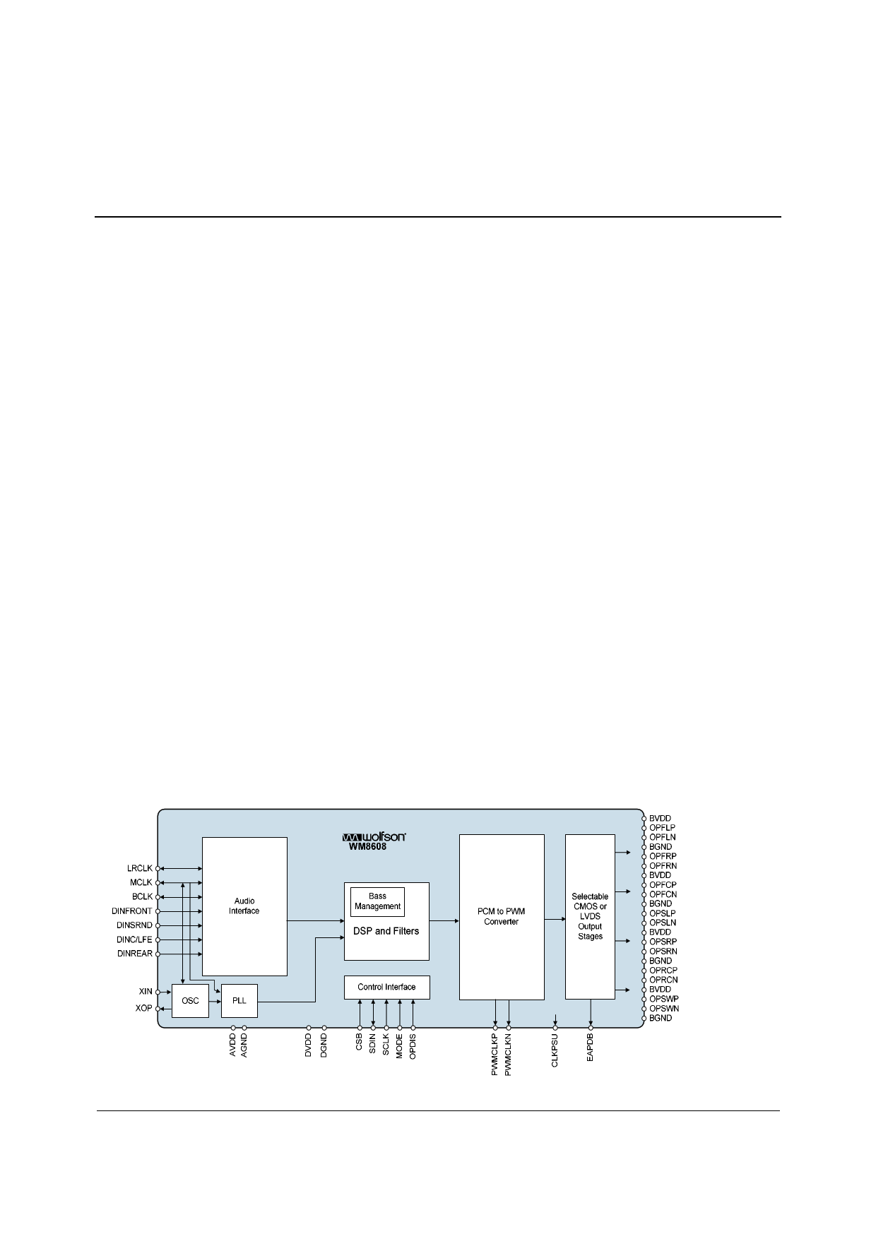
5 to 7.1 Channel PWM Controller
DESCRIPTION
The WM8608 comprises a high performance multi-channel
PWM digital power amplifier controller. Simply by adding
appropriate power output stages a multi-channel power
amplifier may be built. Six identical full audio bandwidth
channels, plus a reduced bandwidth sub channel are
provided as PWM outputs, to drive 6 speakers plus Sub.
The PCM to PWM converter supports up to 7.1 channels of
audio, in PCM input formats. These may be mixed down to
6.1 or 5.1 outputs, by mixing rear channel data into centre
rear or surround speakers if required. If 5.1 channel data is
input, the surround data may be processed internally to
create a pseudo 6.1 signal with rear channel output.
A Graphic Equaliser function is provided, plus selectable
high frequency equalisation to suit different speaker types.
Independent volume control for each channel is provided.
The WM8608 PWM controller is compatible with integrated
switching output stages available from a number of vendors
or alternatively may be used with a discrete output stage
configuration and achieve similar levels of performance.
A Dynamic Peak Compressor with programmable attack
and decay times is included, which allows headroom for
tone control, bass management and extra digital gain to be
provided, without clipping occurring.
A Synchroniser allows slaving to LRCLK, thus making the
WM8608 independent of source MCLK frequency and jitter.
The device is controlled via a 2/3 wire serial interface. The
interface provides access to all features including channel
selection, volume controls, mutes, de-emphasis and power
management facilities. The device is supplied in a 48-pin
TQFP package.
FEATURES
• Multi-channel PWM audio amplifier controller
• Supports Stereo, 5.1, 6.1 or 7.1 inputs
• Supports 2.1, 5.1 or 6.1 outputs with optional rear centre
channel generation
• PWM Audio Performance with typical output stage
− 100dB SNR (‘A’ weighted @ 48kHz)
− 0.01% THD @ 1Watt
− 0.1% THD @ 30Watt
• Integrated Bass Management support with adjustable filter
• Integrated 4-band Graphic Equaliser for 3 front channels
• Adjustable output stage filter compensation for different
speakers
• Volume control on each 6.1 channel +24dB to -103.5dB in
0.5dB steps, with volume ramping and auto-mute
functions
• Programmable Dynamic Peak Compressor avoids clipping
even at high volume settings
• Internal PLL and optional crystal oscillator, supporting
Audio and MPEG standards
• 2/3-Wire MPU Serial Control Interface
• Master or Slave Clocking Mode
• Programmable Audio Data Interface Modes
− I2S, Left, Right Justified or DSP
− 16/20/24/32 bit Word Lengths
• De-emphasis support for stereo
• Selectable CMOS or LVDS digital outputs
APPLICATIONS
• Surround Sound AV Processors and Hi-Fi systems
• Automotive Audio
• DVD receivers
WOLFSON MICROELECTRONICS plc
www.wolfsonmicro.com
Product Preview, March 2004, Rev 1.5
Copyright 2004 Wolfson Microelectronics plc
1 page 
Product Preview
WM8608
PIN DESCRIPTION
PIN NAME
TYPE
DESCRIPTION
1
XOP
Digital Output
Crystal oscillator output connection
2
XIN
Digital Input
Crystal oscillator input connection (may be left unconnected in slave
mode)
3 DGND
Supply
Digital negative supply
4
MCLK
Digital Input/Output Master clock; 256, 384, 512 fs (fs = word clock frequency) or 27MHz
5 DVDD
Supply
Digital positive supply
6
DINFRONT
Digital Input
Front channel data input
7
DINSRND
Digital Input
Surround channel data input
8
DINC_LFE
Digital Input
Centre and surround channel data input
9
DINREAR
Digital Input
Rear channel data for 6.1 and 7.1 inputs
10
LRCLK
Digital Input/Output Left/right word clock
11 BCLK
Digital IO
Audio interface bit clock
12
OPDIS
Digital Input p.d. Output disable
13
MODE
Digital Input p.d. 2/3 Wire control interface mode
14
SCLK
Digital Input
Serial interface clock
15
SDIN
Digital Input/Output Serial interface data
16
CSB
Digital Input
Serial interface load signal
17
EAPDB
Digital Output
External output stage power down
18 BVDD
Supply
PWM output buffer positive supply
19
OPSWN
Digital Output
PWM output negative Subwoofer channel
20
OPSWP
Digital Output
PWM output positive Subwoofer channel
21 BGND
Supply
PWM output buffer ground supply
22
OPRCN
Digital Output
PWM output negative Rear centre (left) channel
23
OPRCP
Digital Output
PWM output positive Rear centre (left) channel
24 BVDD
Supply
PWM output buffer positive supply
25 AGND
Supply
Analogue negative supply
26
CLKPSU
Digital Output
Clock for external PSU
27 BGND
Supply
PWM output buffer ground supply
28
OPSRN
Digital Output
PWM output negative Surround right channel
29
OPSRP
Digital Output
PWM output positive Surround right channel
30 BVDD
Supply
PWM output buffer positive supply
31
OPSLN
Digital Output
PWM output negative Surround left channel
32
OPSLP
Digital Output
PWM output positive Surround left channel
33 BGND
Supply
PWM output buffer ground supply
34
OPFCN
Digital Output
PWM output negative Front centre channel
35
OPFCP
Digital Output
PWM output positive Front centre channel
36 BVDD
Supply
PWM output buffer positive supply
37
OPFRN
Digital Output
PWM output negative Front right channel
38
OPFRP
Digital Output
PWM output positive Front right channel
39 BGND
Supply
PWM output buffer ground supply
40
OPFLN
Digital Output
PWM output negative Front left channel
41
OPFLP
Digital Output
PWM output positive Front left channel
42 BVDD
Supply
PWM output buffer positive supply
43
PWMCLKN
Digital Output
PWM Clock negative
44
PWMCLKP
Digital Output
PWM Clock positive
45 NC Not Connected Do Not Connect
46 NC Not Connected Do Not Connect
47
AVDD
Analogue Supply Analogue positive supply
48
AGND
Analogue Supply Analogue negative supply
Notes: Digital input pins have Schmitt trigger input buffers. Pins marked ‘p.u.’ or ‘p.d.’ have internal pull-up or pull down.
w
PP Rev 1.5 March 2004
5
5 Page 
Product Preview
AUDIO INTERFACE TIMING – SLAVE MODE
tBCH
tBCL
BCLK
tBCY
LRCLK
DINFRONT
DINSRND
DINC_LFE
DINREAR
tDS
tLRH
tDH
tLRSU
WM8608
Figure 3 Digital Audio Data Timing – Slave Mode
Test Conditions
AVDD, DVDD, BVDD = 3.3V, AGND, DGND, BGND = 0V, TA = +25oC, Slave Mode, fs = 48kHz, MCLK = 256fs, 24-bit data,
unless otherwise stated.
PARAMETER
Audio Data Input Timing Information
BCLK cycle time
BCLK pulse width high
BCLK pulse width low
BCLK rise/fall times
LRCLK set-up time to BCLK rising edge
LRCLK hold time from BCLK rising edge
LRCLK rise/fall times
DINFRONT, DINSRND, DINC_LFE and DINREAR hold
time from BCLK rising edge
SYMBOL
tBCY
tBCH
tBCL
tLRSU
tLRH
tDH
MIN
TYP
MAX
UNIT
50 ns
20 ns
20 ns
5 ns
10 ns
10 ns
5 ns
10 ns
Table 5 Audio Interface Timing – Slave Mode
Note: BCLK period should always be greater than or equal to MCLK period.
w
PP Rev 1.5 March 2004
11
11 Page | ||
| Páginas | Total 30 Páginas | |
| PDF Descargar | [ Datasheet WM8608.PDF ] | |
Hoja de datos destacado
| Número de pieza | Descripción | Fabricantes |
| WM8602 | 2.1 CHANNEL PWM CONTROLLER | Wolfson Microelectronics plc |
| WM8608 | 5 TO 7.1 CHANNEL PWM CONTROLLER | Wolfson Microelectronics |
| Número de pieza | Descripción | Fabricantes |
| SLA6805M | High Voltage 3 phase Motor Driver IC. |
Sanken |
| SDC1742 | 12- and 14-Bit Hybrid Synchro / Resolver-to-Digital Converters. |
Analog Devices |
|
DataSheet.es es una pagina web que funciona como un repositorio de manuales o hoja de datos de muchos de los productos más populares, |
| DataSheet.es | 2020 | Privacy Policy | Contacto | Buscar |