|
|
|
PDF TC105 Data sheet ( Hoja de datos )
| Número de pieza | TC105 | |
| Descripción | PFM/PWM Step-Down DC/DC Controller | |
| Fabricantes | Microchip Technology | |
| Logotipo | ||
Hay una vista previa y un enlace de descarga de TC105 (archivo pdf) en la parte inferior de esta página. Total 14 Páginas | ||
|
No Preview Available !
TC105
PFM/PWM Step-Down DC/DC Controller
Features
• 57µA (Typ) Supply Current
• 1A Output Current
• 0.5µA Shutdown Mode
• 300kHz Switching Frequency for Small Inductor
Size
• Programmable Soft-Start
• 92% Typical Efficiency
• Small Package: 5-Pin SOT-23A
Applications
• Palmtops
• Battery-Operated Systems
• Portable Instruments
• Positive LCD Bias Generators
• Portable Communicators
• Hand-Held Scanners
• 5V to 3V Down Converters
Device Selection Table
Part
Number
Output
Voltage
(V)*
Package
Osc.
Freq.
(kHz)
Operating
Temp.
Range
TC105503ECT 5.0 5-Pin SOT-23A 300 -40°C to +85°C
TC105333ECT 3.3 5-Pin SOT-23A 300 -40°C to +85°C
TC105303ECT 3.0 5-Pin SOT-23A 300 -40°C to +85°C
*Other output voltages are available. Please contact
Microchip Technology Inc. for details.
Package Type
5-Pin SOT-23A
VOUT
5
SHDN
4
TC105
1
EXT
2
VDD
3
GND
NOTE: 5-Pin SOT-23A is equivalent to the EIAJ SC-74A
General Description
The TC105 is a step-down (Buck) switching controller
that furnishes output currents of up to 1A (max) while
delivering a typical efficiency of 92%. The TC105
normally operates in pulse width modulation mode
(PWM), but automatically switches to pulse frequency
modulation (PFM) at low output loads for greater
efficiency. Oscillator frequency is 300kHz, allowing use
of small (22µH) inductors. Supply current draw is only
102µA (max), and is reduced to less than 0.5µA when
the SHDN input is brought low. Regulator operation is
suspended during shutdown. The TC105 accepts a
maximum input voltage of 10V.
The TC105 is available in a small 5-Pin SOT-23A
package, occupies minimum board space and is ideal
for a wide range of applications.
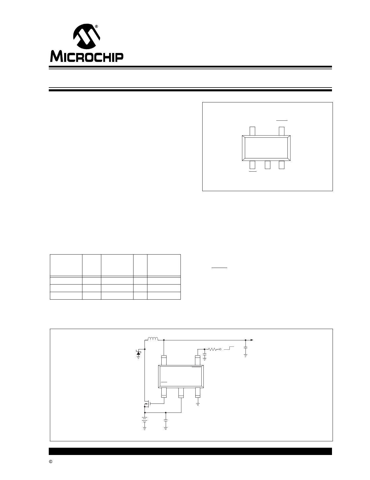
Functional Block Diagram
D1
MA737
L1 22µH (Sumida CD54)
54
VOUT
SHDN
TC105333ECT
EXT
VDD
GND
1 23
RSS 470K
OFF ON
CSS
(From System
Control Logic)
0.033µF
3.3V
VOUT
C2
47µF
10V
Tantalum
Si 9430 P
+
VBATT
6V –
NiMH
C1 10µF/16V
3.3V Regulated Supply Using 6V
NiMH Battery Pack Input
© 2002 Microchip Technology Inc.
DS21349B-page 1
1 page 
3.8 External Switching Transistor
Selection
EXT is a complementary output with a maximum ON
resistance of 22Ω to VDD when high and 19Ω to ground
when low. It is designed to directly drive a P-channel
MOSFET or a PNP bipolar transistor through a base
current limiting resistor (Figure 4-2). A PNP transistor is
recommended in applications where VIN is less than
2.5V. Otherwise, a P-channel MOSFET is preferred as
it affords the highest efficiency because it does not
draw any gate drive current. However, P-channel
MOSFETs are typically more expensive than bipolar
transistors.
P-channel MOSFET selection is determined mainly by
the on-resistance, gate-source threshold, and gate
charge requirements. Also, the drain-to-source and
gate-to-source breakdown voltage ratings must be
greater than VDDMAX. The total gate charge specifica-
tion should be less than 100nC for best efficiency. The
MOSFET must be capable of handling the required
peak inductor current, and should have a very low
on-resistance at that current. For example, an Si9430
MOSFET has a drain-to-source rating of -20V, and a
typical on-resistance rDSON of 0.07Ω at 2A, with VGS =
-4.5V. Table 4-1 lists suppliers of external components
recommended for use with the TC105.
TC105
3.8.1 BOARD LAYOUT GUIDELINES
As with all inductive switching regulators, the TC105
generates fast switching waveforms, which radiate
noise. Interconnecting lead lengths should be mini-
mized to keep stray capacitance, trace resistance and
radiated noise as low as possible. In addition, the GND
pin, input bypass capacitor and output filter capacitor
ground leads should be connected to a single point.
The input capacitor should be placed as close to power
and ground pins of the TC105 as possible. The length
of the EXT trace must also be kept as short as possible.
© 2002 Microchip Technology Inc.
DS21349B-page 5
5 Page 
TC105
Sales and Support
Data Sheets
Products supported by a preliminary Data Sheet may have an errata sheet describing minor operational differences and recom-
mended workarounds. To determine if an errata sheet exists for a particular device, please contact one of the following:
1. Your local Microchip sales office
2. The Microchip Corporate Literature Center U.S. FAX: (480) 792-7277
3. The Microchip Worldwide Site (www.microchip.com)
Please specify which device, revision of silicon and Data Sheet (include Literature #) you are using.
New Customer Notification System
Register on our web site (www.microchip.com/cn) to receive the most current information on our products.
2002 Microchip Technology Inc.
DS21349B-page 11
11 Page | ||
| Páginas | Total 14 Páginas | |
| PDF Descargar | [ Datasheet TC105.PDF ] | |
Hoja de datos destacado
| Número de pieza | Descripción | Fabricantes |
| TC100 | Ceramic Disc Capacitor | Cosonic Enterprise |
| TC100PA | (TC Series) Thick Film on Porceleinized Steel Substrate | Ohmite Manufacturing |
| TC1014 | CMOS LDOs | Microchip Technology |
| TC1014 | 50mA CMOS LDO WITH SHUTDOWN AND REFERENCE BYPASS | TelCom Semiconductor |
| Número de pieza | Descripción | Fabricantes |
| SLA6805M | High Voltage 3 phase Motor Driver IC. |
Sanken |
| SDC1742 | 12- and 14-Bit Hybrid Synchro / Resolver-to-Digital Converters. |
Analog Devices |
|
DataSheet.es es una pagina web que funciona como un repositorio de manuales o hoja de datos de muchos de los productos más populares, |
| DataSheet.es | 2020 | Privacy Policy | Contacto | Buscar |