|
|
|
PDF UC3633 Data sheet ( Hoja de datos )
| Número de pieza | UC3633 | |
| Descripción | Phase Locked Frequency Controller | |
| Fabricantes | Unitrode | |
| Logotipo | ||
Hay una vista previa y un enlace de descarga de UC3633 (archivo pdf) en la parte inferior de esta página. Total 8 Páginas | ||
|
No Preview Available !
Phase Locked Frequency Controller
UC1633
UC2633
UC3633
FEATURES
• Precision Phase Locked Frequency
Control System
• Crystal Oscillator
• Programmable Reference Frequency
Dividers
• Phase Detector with Absolute Frequency
Steering
• Digital Lock Indicator
• Double Edge Option on the Frequency
Feedback Sensing Amplifier
• Two High Current Op-Amps
• 5V Reference Output
DESCRIPTION
The UC1633 family of integrated circuits was designed for use in phase
locked frequency control loops. While optimized for precision speed
control of DC motors, these devices are universal enough for most ap-
plications that require phase locked control. A precise reference fre-
quency can be generated using the device’s high frequency oscillator
and programmable frequency dividers. The oscillator operates using a
broad range of crystals, or, can function as a buffer stage to an external
frequency source.
The phase detector on these integrated circuits compares the refer-
ence frequency with a frequency/phase feedback signal. In the case of
a motor, feedback is obtained at a hall output of other speed detection
device. This signal is buffered by a sense ampilfier that squares up the
signal as it goes into the digital phase detector. The phase detector re-
sponds proportionally to the phase error between the reference and the
sense amplifier output. This phase detector includes absolute fre-
quency steering to provide maximum drive signals when any frequency
error exists. This feature allows optimum start-up and lock times to be
realized.
Two op-amps are included that can be configured to provide necessary
loop filtering. The outputs of the op-amps will source or sink in excess
of 16mA, so they can provide a low impedence control signal to driving
circuits.
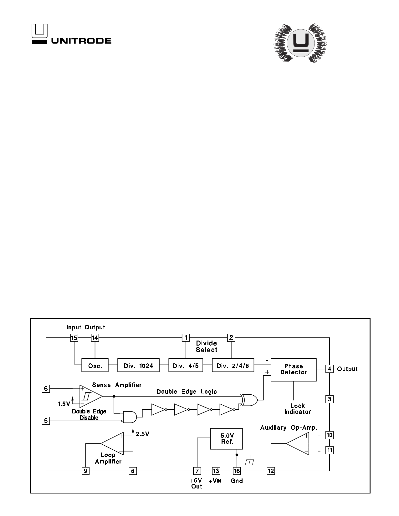
BLOCK DIAGRAM
Additional features include a double edge option on the sense amplifier
that can be used to double the loop reference frequency for increased
loop bandwidths. A digital lock signal is provided that indicates when
there is zero frequency error, and a 5V reference output allows DC op-
erating levels to be accurately set.
4/97
1
1 page 
APPLICATION AND OPERATION INFORMATION
Phase Detector Operation
The phase detector on these devices is a digital circuit
that responds to the rising edges of the detector’s two in-
puts. The phase detector output has three states: a high,
5V state, a low, 0V state, and a middle, 2.5V state. In the
high and low states the output impedance of the detector
is low and the middle state output impedence is high, typi-
cally 6.0kΩ. When there is any static frequency difference
between the inputs, the detector output is fixed at its high
level if the +input (the sense amplifier signal) is greater in
frequency, and fixed at its low level if the -input (the refer-
ence frequency signal) is greater in frequency.
When the frequencies of the two inputs to the detector
are equal, the phase detector switches between its middle
state and either the high or low states, depending on the
relative phase of the two signals. If the +input is leading in
phase then, during each period of the input frequency, the
detector output will be high for a time equal to the time dif-
ference between the rising edges of the inputs, and will
be at its middle level for the remainder of the period. If the
phase relationship is reversed, then the detector will go
low for a time proportional to the phase difference of the
inputs. The resulting gain of the phase detector. kø, is
UC1633
UC2633
UC3633
5V/4π radians or about 0.4V/radian. The dynamic range of
the detector is ±2π radians.
The operation of the phase detector is illustrated in the
figures below. The upper figure shows typical voltage
waveforms seen at the detector output for leading and
lagging phase conditions. The lower figure is a state dia-
gram of the phase detector logic. In this figure, the circles
represent the 10 possible states of the logic, and the con-
necting arrows represent the transition events/paths to
and from these states. Transition arrows that have a clock-
wise rotation are the result of a rising edge on the +input,
and conversely, those with counter-clockwise rotation are
tied to the rising edge of the -input signal.
The normal operational states of the logic are 6 and 7 for
positive phase error, 1 and 2 for a negative phase error.
States 8 and 9 occur during positive frequency error, 3
and 4 during negative frequency error. States 5 and 10
occur only as the inputs cross over from the frequency er-
ror to a normal phase error only condition. The level of the
phase detector output is determined by the logic state as
defined in the state diagram figure. The lock indicator out-
put is high, off, when the detector is in states 1, 2, 6, or 7.
Typical Phase Detector Output Waveforms
Phase Detector State Diagram
5
5 Page | ||
| Páginas | Total 8 Páginas | |
| PDF Descargar | [ Datasheet UC3633.PDF ] | |
Hoja de datos destacado
| Número de pieza | Descripción | Fabricantes |
| UC3633 | Phase Locked Frequency Controller | Unitrode |
| UC3634 | Phase Locked Frequency Controller | Unitrode |
| UC3634 | Phase Locked Frequency Controller | Texas Instruments |
| UC3635 | Phase Locked Frequency Controller | Unitrode |
| Número de pieza | Descripción | Fabricantes |
| SLA6805M | High Voltage 3 phase Motor Driver IC. |
Sanken |
| SDC1742 | 12- and 14-Bit Hybrid Synchro / Resolver-to-Digital Converters. |
Analog Devices |
|
DataSheet.es es una pagina web que funciona como un repositorio de manuales o hoja de datos de muchos de los productos más populares, |
| DataSheet.es | 2020 | Privacy Policy | Contacto | Buscar |