|
|
|
PDF UC3637 Data sheet ( Hoja de datos )
| Número de pieza | UC3637 | |
| Descripción | Switched Mode Controller for DC Motor Drive | |
| Fabricantes | Unitrode | |
| Logotipo | ||
Hay una vista previa y un enlace de descarga de UC3637 (archivo pdf) en la parte inferior de esta página. Total 7 Páginas | ||
|
No Preview Available !
Switched Mode Controller for DC Motor Drive
UC1637
UC2637
UC3637
FEATURES
• Single or Dual Supply
Operation
• ±2.5V to ±20V Input Supply
Range
• ±5% Initial Oscillator
Accuracy; ± 10% Over
Temperature
• Pulse-by-Pulse Current
Limiting
• Under-Voltage Lockout
• Shutdown Input with
Temperature Compensated
2.5V Threshold
• Uncommitted PWM
Comparators for Design
Flexibility
• Dual 100mA, Source/Sink
Output Drivers
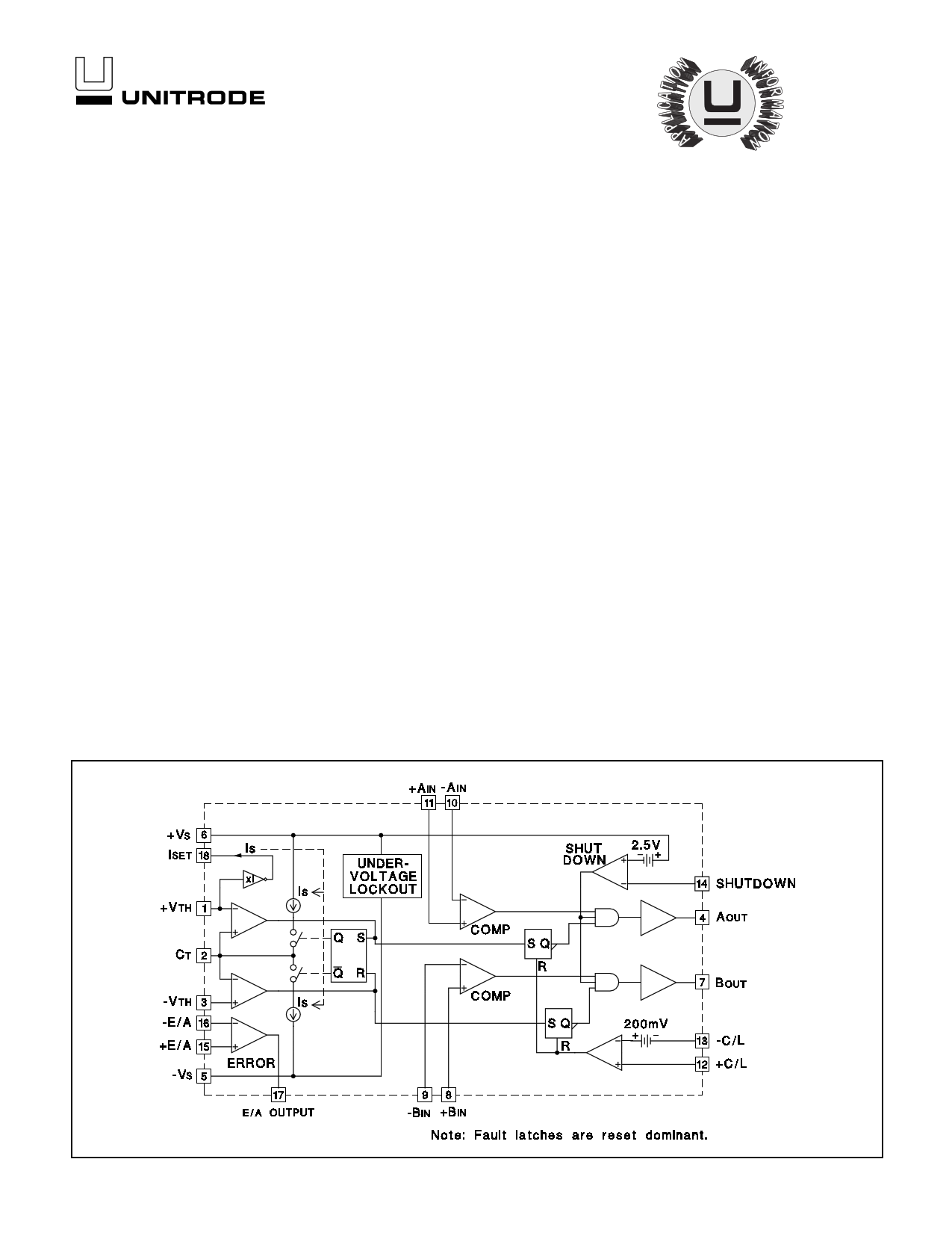
BLOCK DIAGRAM
DESCRIPTION
The UC1637 is a pulse width modulator circuit intended to be used for a variety of
PWM motor drive and amplifier applications requiring either uni-directional or bi-
directional drive circuits. When used to replace conventional drivers, this circuit
can increase efficiency and reduce component costs for many applications. All
necessary circuitry is included to generate an analog error signal and modulate
two bi-directional pulse train outputs in proportion to the error signal magnitude
and polarity.
This monolithic device contains a sawtooth oscillator, error amplifier, and two
PWM comparators with ±100mA output stages as standard features. Protection
circuitry includes under-voltage lockout, pulse-by-pulse current limiting, and a
shutdown port with a 2.5V temperature compensated threshold.
The UC1637 is characterized for operation over the full military temperature range
of -55°C to +125°C, while the UC2637 and UC3637 are characterized for -25°C to
+85°C and 0°C to +70°C, respectively.
ABSOLUTE MAXIMUM RATINGS (Note 1)
Supply Voltage (±Vs) . . . . . . . . . . . . . . . . . . . . . . . . . . . . . . . . . . . . . . . . . . . . . . . . . . . ±20V
Output Current, Source/Sink (Pins 4, 7) . . . . . . . . . . . . . . . . . . . . . . . . . . . . . . . . . . . 500mA
Analog Inputs (Pins 1, 2, 3, 8, 9, 10, 11 12, 13, 14, 15, 16) . . . . . . . . . . . . . . . . . . . . . . . ±Vs
Error Amplifier Output Current (Pin 17) . . . . . . . . . . . . . . . . . . . . . . . . . . . . . . . . . . . ±20mA
Oscillator Charging Current (Pin 18). . . . . . . . . . . . . . . . . . . . . . . . . . . . . . . . . . . . . . . -2mA
Power Dissipation at TA = 25°C (Note 2) . . . . . . . . . . . . . . . . . . . . . . . . . . . . . . . . 1000mW
Power Dissipation at TC = 25°C (Note 2) . . . . . . . . . . . . . . . . . . . . . . . . . . . . . . . . 2000mW
Storage Temperature Range . . . . . . . . . . . . . . . . . . . . . . . . . . . . . . . . . . . -65°C to +150°C
Lead Temperature (Soldering, 10 Seconds). . . . . . . . . . . . . . . . . . . . . . . . . . . . . . . . +300°C
Note 1: Currents are positive into, negative out of the specified terminal.
Note 2: Consult Packaging Section of Databook for thermal limitations and considerations
of package.
6/97
1 page 
UC1637
UC2637
UC3637
Figure 3. Modulation Schemes Showing (A) Zero Deadtime (B) Deadtime and (C) Deadband Configurations
Shutdown Comparator
The shutdown terminal may be used for implementing
various shutdown and protection schemes. By pulling the
terminal more than 2.5V below VIN, the output drivers will
be enabled. This can be realized using an open collector
gate or NPN transistor biased to either ground or the
negative supply. Since the threshold is temperature stabi-
lized, the comparator can be used as an accurate low
voltage lockout (Figure 4) and/or delayed start as in Fig-
ure 5. In the shutdown mode the outputs are held in the
low state.
Figure 5. Delayed Start-Up
-VS to within 3V of the +VS supply while providing excel-
lent noise rejection. Figure 6 shows a typical current
sense circuit.
Figure 4. External Under-Voltage Lockout
Current Limit
A latched current limit amplifier with an internal 200mV
offset is provided to allow pulse-by-pulse current limiting.
Differential inputs will accept common mode signals from
Figure 6. Current Limit Sensing
5
5 Page | ||
| Páginas | Total 7 Páginas | |
| PDF Descargar | [ Datasheet UC3637.PDF ] | |
Hoja de datos destacado
| Número de pieza | Descripción | Fabricantes |
| UC3633 | Phase Locked Frequency Controller | Unitrode |
| UC3634 | Phase Locked Frequency Controller | Unitrode |
| UC3634 | Phase Locked Frequency Controller | Texas Instruments |
| UC3635 | Phase Locked Frequency Controller | Unitrode |
| Número de pieza | Descripción | Fabricantes |
| SLA6805M | High Voltage 3 phase Motor Driver IC. |
Sanken |
| SDC1742 | 12- and 14-Bit Hybrid Synchro / Resolver-to-Digital Converters. |
Analog Devices |
|
DataSheet.es es una pagina web que funciona como un repositorio de manuales o hoja de datos de muchos de los productos más populares, |
| DataSheet.es | 2020 | Privacy Policy | Contacto | Buscar |