|
|
|
PDF HC5509 Data sheet ( Hoja de datos )
| Número de pieza | HC5509 | |
| Descripción | Impedance Matching Design Equations | |
| Fabricantes | Intersil | |
| Logotipo | ||
Hay una vista previa y un enlace de descarga de HC5509 (archivo pdf) en la parte inferior de esta página. Total 7 Páginas | ||
|
No Preview Available !
Impedance Matching Design Equations for the
TM HC5509 Series of SLICs
Application Note
October 1996
AN9607.1
Introduction
The HC5509 Series of SLICs use feedback to synthesize the
impedance at the 2-wire tip and ring terminals. The network
is capable of synthesizing both resistive and complex imped-
ances. Matching the SLIC’s 2-wire impedance to the load is
important to maximize power transfer and 2-wire return loss.
The 2-wire return loss is a measure of the similarity of the
impedance of a transmission line (tip and ring) and the
impedance at it’s termination. It is a ratio, expressed in deci-
bels, of the power of the outgoing signal to the power of the
signal reflected back from an impedance discontinuity.
This application note will discuss the basic DC operation of
the tip and ring amplifiers for an understanding of the reac-
tion between the tip and ring amplifiers, the requirements for
impedance matching and the derivation of the design equa-
tions for calculating the required feedback components for
both resistive and complex impedances. The analysis will
use the HC5509B as the basis for the discussion. Design
solutions for the HC5509A1R3060, HC5524 and HC5517
are provided in Table 1.
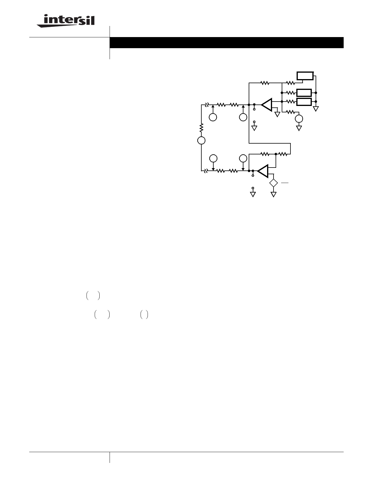
Tip and Ring Amplifiers
The tip and ring amplifiers are voltage feedback op amps
that are connected to generate a differential output (e.g. if tip
sources 20mA then ring sinks 20mA). Figure 1 shows the
connection of the tip and ring amplifiers. The tip DC voltage
is set by an internal +2V reference, resulting in -4V at the
output. The ring DC voltage is set by the tip DC output volt-
age and an internal VBAT/2 reference, resulting in VBAT +4V
at the output (see Equations 1, 2 and 3).
VTIP FEED
=
VC
=
–2
V
R----R--⁄---2-
=
–4V
VRING
FEED
=
VD
=
V-----B-2---A---T--
1
+
RR---
–
VTIP
F
E
E
D
RR---
(EQ. 1)
(EQ. 2)
VD = VBAT + 4
(EQ. 3)
R
TIP FEED
RB1 RB2
AC
-
+ VC
-
+
RL
2R VOUT1 GROUNDED
FOR DC
2R ANALYSIS
VFB
R
VRX
R/2
+
-
2VDC
+
-
∆VIN
RR
BD
RB3 RB4
RING FEED
-
+
+
-
VD
+-
VBAT
2
FIGURE 1. OPERATION OF THE TIP AND RING AMPLIFIERS
Requirements for Impedance matching
Impedance matching of the HC5509B application circuit to
the transmission line requires that the impedance be
matched to points “A” and “B” in Figure 2. To do this, the
sense resistors RB1, RB2, RB3 and RB4 must be accounted
for by the feedback network to make it appear as if the out-
put of the tip and ring amplifiers are at points “A” and “B”.
The feedback network takes a voltage that is equal to the
voltage drop across the sense resistors and feeds it into the
summing node of the tip amplifier. The effect of this is to
cause the tip feed voltages to become more negative by a
value that is proportional to the voltage drop across the
sense resistors RB1 and RB2. At the same time the ring
amplifier becomes more positive by the same amount to
account for resistors RB3 and RB4.
The net effect cancels out the voltage drop across the feed
resistors. By nullifying the effects of the feed resistors the
feedback circuitry becomes relatively easy to match the
impedance at points “A” and “B”.
1 CAUTION: These devices are sensitive to electrostatic discharge; follow proper IC Handling Procedures.
1-888-INTERSIL or 321-724-7143 | Intersil (and design) is a trademark of Intersil Americas Inc.
Copyright © Intersil Americas Inc. 2001. All Rights Reserved
1 page 
LOAD
IMPEDANCE
150Ω
820Ω
0.072µF
Application Note 9607
TABLE 1. (Continued)
KRF
40kΩ
KZO
15kΩ
82kΩ
720pF
780Ω
160Ω
0.115µF
40kΩ
78kΩ
16kΩ
1.15nF
820Ω
220Ω
0.115µF
40kΩ
82kΩ
22kΩ
1.15nF
620Ω
370Ω
0.310µF
40kΩ
HC5524: VFB CONNECTED. Single feed resistor for tip and one for ring.
62kΩ
37kΩ
3.1nF
600Ω
20kΩ
50kΩ
900Ω
600Ω
2.2µF
725Ω
2.2µF
900Ω
2.2µF
20kΩ
20kΩ
20kΩ
20kΩ
80kΩ
50kΩ
22nF
62.5kΩ
22nF
80kΩ
22nF
OPTIONAL PARALLEL
RESISTOR
NA
NA
NA
NA
NA
NA
360kΩ
360kΩ
360kΩ
5
5 Page | ||
| Páginas | Total 7 Páginas | |
| PDF Descargar | [ Datasheet HC5509.PDF ] | |
Hoja de datos destacado
| Número de pieza | Descripción | Fabricantes |
| HC5500M03 | Hybrid Coupler | Yantel |
| HC5503 | Low Cost 24V SLIC For PABX/Key Systems | Intersil Corporation |
| HC5503C | Unbalanced PBX/Key System SLIC/ Subscriber Line Interface Circuit | Intersil Corporation |
| HC5503T | Balanced PBX/Key System SLIC/ Subscriber Line Interface Circuit | Intersil Corporation |
| Número de pieza | Descripción | Fabricantes |
| SLA6805M | High Voltage 3 phase Motor Driver IC. |
Sanken |
| SDC1742 | 12- and 14-Bit Hybrid Synchro / Resolver-to-Digital Converters. |
Analog Devices |
|
DataSheet.es es una pagina web que funciona como un repositorio de manuales o hoja de datos de muchos de los productos más populares, |
| DataSheet.es | 2020 | Privacy Policy | Contacto | Buscar |