|
|
|
PDF MAX3941ETG Data sheet ( Hoja de datos )
| Número de pieza | MAX3941ETG | |
| Descripción | 10Gbps EAM Driver with Integrated Bias Network | |
| Fabricantes | Maxim Integrated | |
| Logotipo | ||
Hay una vista previa y un enlace de descarga de MAX3941ETG (archivo pdf) en la parte inferior de esta página. Total 11 Páginas | ||
|
No Preview Available !
19-2935; Rev 0; 7/03
10Gbps EAM Driver with Integrated
Bias Network
General Description
The MAX3941 is designed to drive an electro-absorp-
tion modulator (EAM) at data rates up to 10.7Gbps. It
incorporates the functions of a biasing circuit and a
modulation circuit, with integrated control op amps
externally programmed by DC voltages.
The integrated bias circuit provides a programmable
biasing current up to 50mA. This bias current reflects a
bias voltage of up to 1.25V on an external 50Ω load. The
bias and modulation circuits are internally connected on
chip, eliminating the need for an external bias inductor.
A high-bandwidth, fully differential signal path is internally
implemented to minimize jitter accumulation. When a
clock signal is available, the integrated data-retiming
function can be selected to reject input-signal jitter.
The MAX3941 receives differential CML signals (ground
referenced) with on-chip line terminations of 50Ω. The
output has a 50Ω resistor for back termination and is
able to deliver a modulation current of 40mAP-P to
120mAP-P, with an edge speed of 23ps (20% to 80%
typ). This modulation current reflects an EAM modula-
tion voltage of 1.0VP-P to 3.0VP-P.
The MAX3941 also includes an adjustable pulse-width
control circuit to precompensate for asymmetrical EAM
characteristics. It is available in a compact 4mm x
4mm, 24-pin thin QFN package and operates over the
-40°C to +85°C temperature range.
Features
o On-Chip Bias Network
o 23ps Edge Speed
o Programmable Modulation Voltage Up to 3VP-P
o Programmable EAM Biasing Voltage Up to 1.25V
o Selectable Data-Retiming Latch
o Up to 10.7Gbps Operation
o Integrated Modulation and Biasing Functions
o 50Ω On-Chip Input and Output Terminations
o Pulse-Width Adjustment
o Enable and Polarity Controls
o ESD Protection
Ordering Information
PART
MAX3941ETG
TEMP RANGE
-40°C to +85°C
PIN-PACKAGE
24-Thin QFN
(4mm x 4mm)
Applications
SONET OC-192 and SDH STM-64
Transmission Systems
DWDM Systems
Long/Short-Reach Optical Transmitters
10Gbps Ethernet
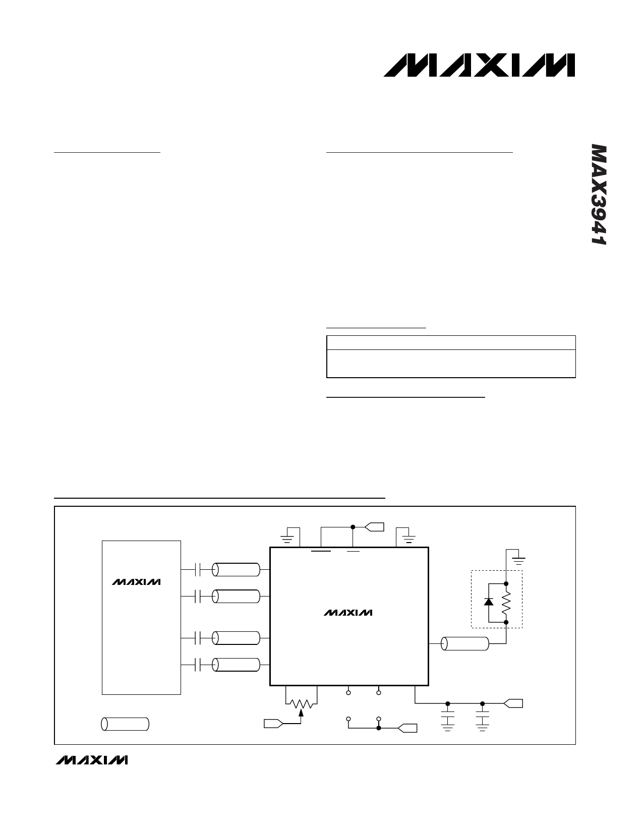
Typical Application Circuit
-5.2V
MAX3952
DATA+
DATA-
0.01µF
0.01µF
50Ω
50Ω
PLRT MODEN
DATA+
RTEN
DATA-
GND
10Gbps
SERIALIZER
CLK+
CLK-
0.01µF
0.01µF
50Ω
50Ω
REPRESENTS A CONTROLLED-
IMPEDANCE TRANSMISSION LINE.
-5.2V
MAX3941
CLK+
CLK-
PWC+ PWC-
2kΩ
MODSET BIASSET
+
VMODSET
-
+
VBIASSET
-
OUT
VEE
-5.2V
EAM
50Ω
330pF
-5.2V
0.1µF
________________________________________________________________ Maxim Integrated Products 1
For pricing, delivery, and ordering information, please contact Maxim/Dallas Direct! at
1-888-629-4642, or visit Maxim’s website at www.maxim-ic.com.
1 page 
10Gbps EAM Driver with Integrated
Bias Network
Test Circuits and Timing Diagrams (continued)
CLK+
CLK-
DATA-
DATA+
tSU tHD
VIS = 0.1VP-P TO 1VP-P
DC-COUPLED
0.1VP-P TO 0.8VP-P
AC-COUPLED
VIS
(DATA+) -
(DATA-)
IOUT
NOTE: IOUT RELATES TO RETIMED DATA.
Figure 3. Setup and Hold Timing Definition
VID = 0.2VP-P TO 2VP-P
DC-COUPLED
0.2VP-P TO 1.6VP-P
AC-COUPLED
IMOD = 40mAP-P TO 120mAP-P
IBIAS = 0mA TO 50mA
PATTERN
GENERATOR
GND RTEN PWC+ PWC- GND GND1 GND2
50Ω 50Ω
50Ω 50Ω
50Ω CLK+
CLK-
50Ω
P
W
C
50Ω DATA+
50Ω DATA-
DQ 0
M
U
X
1
IMOD
ROUT
50Ω
OUT
IOUT
OSCILLOSCOPE
50Ω
50Ω
ZL
IBIAS
50Ω 50Ω
VEE VEE
-5.2V
0.1µF
VEE
300pF
Figure 4. AC-Characterization Circuit
MODSET
VMODSET
VEE
BIASSET
VBIASSET
VEE
_______________________________________________________________________________________ 5
5 Page 
DATA+/CLK+
DATA-/CLK-
10Gbps EAM Driver with Integrated
Bias Network
GND
50Ω 50Ω
MAX3941
GND1 GND2
50Ω
50Ω
GND
MAX3941
50Ω
GND
OUT
VEE
VEE
Figure 7. Simplified Input Circuit
Figure 8. Simplified Output Circuit
TOP VIEW
DATA+ 1
DATA- 2
GND 3
GND 4
CLK+ 5
CLK- 6
Pin Configuration
MAX3941
18 VEE
17 GND2
16 OUT
15 GND1
14 GND
13 VEE
Package Information
For the latest package outline information, go to www.maxim-
ic.com/packages.
PART
MAX3941ETG
PACKAGE TYPE
24-Thin QFN
4mm x 4mm x 0.8mm
PACKAGE CODE
T2444-1
Chip Information
TRANSISTOR COUNT: 1918
PROCESS: SiGe Bipolar
THIN QFN (4mm x 4mm)
EXPOSED PAD CONNECTED TO GROUND
Maxim cannot assume responsibility for use of any circuitry other than circuitry entirely embodied in a Maxim product. No circuit patent licenses are
implied. Maxim reserves the right to change the circuitry and specifications without notice at any time.
Maxim Integrated Products, 120 San Gabriel Drive, Sunnyvale, CA 94086 408-737-7600 ____________________ 11
© 2003 Maxim Integrated Products
Printed USA
is a registered trademark of Maxim Integrated Products.
11 Page | ||
| Páginas | Total 11 Páginas | |
| PDF Descargar | [ Datasheet MAX3941ETG.PDF ] | |
Hoja de datos destacado
| Número de pieza | Descripción | Fabricantes |
| MAX3941ETG | 10Gbps EAM Driver with Integrated Bias Network | Maxim Integrated |
| Número de pieza | Descripción | Fabricantes |
| SLA6805M | High Voltage 3 phase Motor Driver IC. |
Sanken |
| SDC1742 | 12- and 14-Bit Hybrid Synchro / Resolver-to-Digital Converters. |
Analog Devices |
|
DataSheet.es es una pagina web que funciona como un repositorio de manuales o hoja de datos de muchos de los productos más populares, |
| DataSheet.es | 2020 | Privacy Policy | Contacto | Buscar |