|
|
|
PDF OPA2541 Data sheet ( Hoja de datos )
| Número de pieza | OPA2541 | |
| Descripción | Dual High Power OPERATIONAL AMPLIFIER | |
| Fabricantes | Burr-Brown | |
| Logotipo | ||
Hay una vista previa y un enlace de descarga de OPA2541 (archivo pdf) en la parte inferior de esta página. Total 8 Páginas | ||
|
No Preview Available !
® OPA2541
Dual High Power
OPERATIONAL AMPLIFIER
FEATURES
q OUTPUT CURRENTS TO 5A
q POWER SUPPLIES TO ±40V
q FET INPUT
q ELECTRICALLY ISOLATED CASE
APPLICATIONS
q MOTOR DRIVER
q SERVO AMPLIFIER
q SYNCRO/RESOLVER EXCITATION
q VOICE COIL DRIVER
q BRIDGE AMPLIFIER
q PROGRAMMABLE POWER SUPPLY
q AUDIO AMPLIFIER
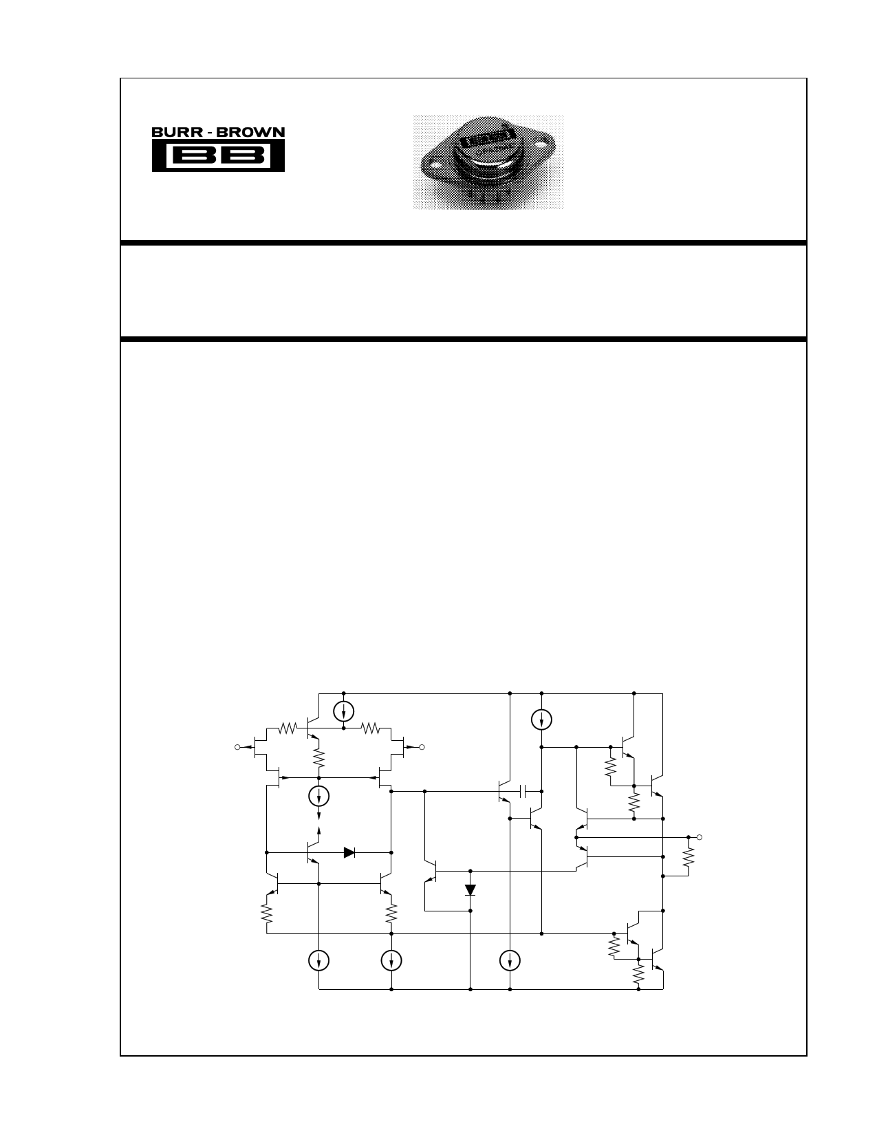
DESCRIPTION
The OPA2541 is a dual power operational amplifier
capable of operation from power supplies up to ±40V
and output currents of 5A continuous. With two mono-
lithic power amplifiers in a single package it provides
unequaled functional density.
The industry-standard 8-pin TO-3 package is isolated
from all internal circuitry allowing it to be mounted
directly to a heat sink without insulators which de-
grade thermal performance. Internal circuitry limits
output current to approximately 6A.
The OPA2541 is available in both industrial and
military temperature range versions.
+VS (2)
–In
(4, 8)
+In
(3, 7)
Out
(5, 1)
–VS (6)
International Airport Industrial Park • Mailing Address: PO Box 11400 • Tucson, AZ 85734 • Street Address: 6730 S. Tucson Blvd. • Tucson, AZ 85706
Tel: (520) 746-1111 • Twx: 910-952-1111 • Cable: BBRCORP • Telex: 066-6491 • FAX: (520) 889-1510 • Immediate Product Info: (800) 548-6132
©1987 Burr-Brown Corporation
PDS-768B
Printed in U.S.A. October, 1993
1 page 
TYPICAL PERFORMANCE CURVES (CONT)
TA = +25°C and VS = ±35VDC, unless otherwise noted.
DYNAMIC RESPONSE
DYNAMIC RESPONSE
ZLOAD = ∞, VS = ±35V, AV = +1
ZLOAD = 4700pF, VS = ±35V, AV = +1
INSTALLATION
INSTRUCTIONS
POWER SUPPLIES
The OPA2541 is specified for operation from power sup-
plies up to ±40V. It can also be operated from an unbalanced
or a single power supply so long as the total power supply
voltage does not exceed 80V (70V for “AM” grade). The
power supplies should be bypassed with low series imped-
ance capacitors such as ceramic or tantalum. These should
be located as near as practical to the amplifier’s power
supply pins. Good power amplifier circuit layout is, in
general, like good high-frequency layout. Consider the path
of large power supply and output currents. Avoid routing
these connections near low-level input circuitry to avoid
waveform distortion and instability.
Signal dependent load current can modulate the power
supply voltage with inadequate power supply bypassing.
This can affect both amplifiers’ outputs. Since the second
amplifier’s signal may not be related to the first, this will
degrade the inherent channel separation of the OPA2541.
HEAT SINKING
Most applications will require a heat sink to prevent junction
temperatures from exceeding the 150°C maximum rating.
The type of heat sink required will depend on the output
signals, power dissipation of each amplifier, and ambient
temperature. The thermal resistance from junction-to-case,
θJC, depends on how the power dissipation is distributed on
the amplifier die.
DC output concentrates the power dissipation in one output
transistor. AC output distributes the power dissipation equally
between the two output transistors and therefore has lower
thermal resistance. Similarly, the power dissipation may be
all in one amplifier (worst case) or equally distributed
between the two amplifiers (best case). Thermal resistances
are provided for each of these possibilities. The case-to-
junction temperature rise is the product of the power dissi-
pation (total of both amplifiers) times the appropriate ther-
mal resistance—
∆ TJC = (PD total) (θJC).
Sufficient heat sinking must be provided to keep the case
temperature within safe limits for the maximum ambient
temperature and power dissipation. The thermal resistance
of the heat sink required may be calculated by:
θHS
=
(150°C
–
∆
T
JC
–
T )/P .
AD
Commercially available heat sinks usually specify thermal
resistance. These ratings are often suspect, however, since
they depend greatly on the mounting environment and air
flow conditions. Actual thermal performance should be
verified by measurement of case temperature under the
required load and environmental conditions.
No insulating hardware is required when using the OPA2541.
Since mica and other similar insulators typically add
0.7°C/W thermal resistance, this is a significant advantage.
See Burr-Brown Application Note AN-83 for further details
on heat sinking.
SAFE OPERATING AREA
The Safe Operating Area (SOA) curve provides comprehen-
sive information on the power handling abilities of the
OPA2541. It shows the allowable output current as a func-
tion of the voltage across the conducting output transistor
(see Figure 1). This voltage is equal to the power supply
voltage minus the output voltage. For example, as the
amplifier output swings near the positive power supply
voltage, the voltage across the output transistor decreases
and the device can safely provide large output currents
demanded by the load.
®
5 OPA2541
5 Page | ||
| Páginas | Total 8 Páginas | |
| PDF Descargar | [ Datasheet OPA2541.PDF ] | |
Hoja de datos destacado
| Número de pieza | Descripción | Fabricantes |
| OPA2541 | Dual High Power Operational Amplifier | Texas Instruments |
| OPA2541 | Dual High Power OPERATIONAL AMPLIFIER | Burr-Brown |
| OPA2544 | High-Voltage High-Current Dual Operational Amplifier | Texas Instruments |
| OPA2544 | High-Voltage / High-Current DUAL OPERATIONAL AMPLIFIER | Burr-Brown |
| Número de pieza | Descripción | Fabricantes |
| SLA6805M | High Voltage 3 phase Motor Driver IC. |
Sanken |
| SDC1742 | 12- and 14-Bit Hybrid Synchro / Resolver-to-Digital Converters. |
Analog Devices |
|
DataSheet.es es una pagina web que funciona como un repositorio de manuales o hoja de datos de muchos de los productos más populares, |
| DataSheet.es | 2020 | Privacy Policy | Contacto | Buscar |