|
|
|
PDF MAX2683 Data sheet ( Hoja de datos )
| Número de pieza | MAX2683 | |
| Descripción | 3.5GHz Downconverter Mixers with Selectable LO Doubler | |
| Fabricantes | Maxim Integrated | |
| Logotipo | ||
Hay una vista previa y un enlace de descarga de MAX2683 (archivo pdf) en la parte inferior de esta página. Total 18 Páginas | ||
|
No Preview Available !
19-1620; Rev 0; 1/00
EVFAOLLULAOTWIOSNDKAITTAMSAHNEUEATL
3.5GHz Downconverter Mixers
with Selectable LO Doubler
General Description
The MAX2683/MAX2684 are super-high-performance,
low-cost downconverter mixers intended for wireless
local loop (WLL) and digital microwave radio (DMR)
applications in the 3.4GHz to 3.8GHz frequency band.
The MAX2683 is optimized for downconversion to IF
frequencies between 100MHz and 400MHz, and allows
both high-side and low-side local oscillator (LO) injec-
tion. The MAX2684 is optimized for IF frequencies
between 800MHz and 1000MHz, and allows low-side
LO injection. A logic-level control enables an internal
frequency doubler on both devices, allowing the exter-
nal LO source to run at full or half frequency. An internal
LO filter reduces LO harmonics and spurious mixing.
The MAX2683/MAX2684 feature an externally adjustable
bias control, set with a single resistor, that lets the user
trade supply current for linearity to optimize system per-
formance. These devices use a double-balanced
Gilbert-cell architecture with single-ended RF and LO
inputs and differential open-collector IF output ports.
Differential IF ports provide a wideband, flexible inter-
face for either single-ended or differential applications.
The MAX2683/MAX2684 operate from a single +2.7V to
+5.5V supply. The devices are packaged in an ultra-
small 16-pin TSSOP-EP package with an exposed pad-
dle for optimum performance at 3.5GHz.
________________________Applications
Wireless Local Loop (WLL)
Digital Microwave Radio (DMR)
Wireless Broadband Access
Features
o 3.4GHz to 3.8GHz RF Frequency Range
o 100MHz to 400MHz IF Frequency Range
(MAX2683)
800MHz to 1000MHz IF Frequency Range
(MAX2684)
o Logic-Enabled LO Frequency Doubler
o Conversion Gain
+6.7dB (MAX2683)
+1dB (MAX2684)
o Programmable IIP3
+7dBm to +11dBm (MAX2683)
+8dBm to +12dBm (MAX2684)
o +2.7V to +5.5V Single-Supply Operation
o Ultra-Small 16-Pin TSSOP-EP Package
PART
MAX2683EUE
MAX2684EUE
*Exposed pad
Ordering Information
TEMP. RANGE
-40°C to +85°C
-40°C to +85°C
PIN-PACKAGE
16 TSSOP-EP*
16 TSSOP-EP*
Typical Operating Circuit appears at end of data sheet.
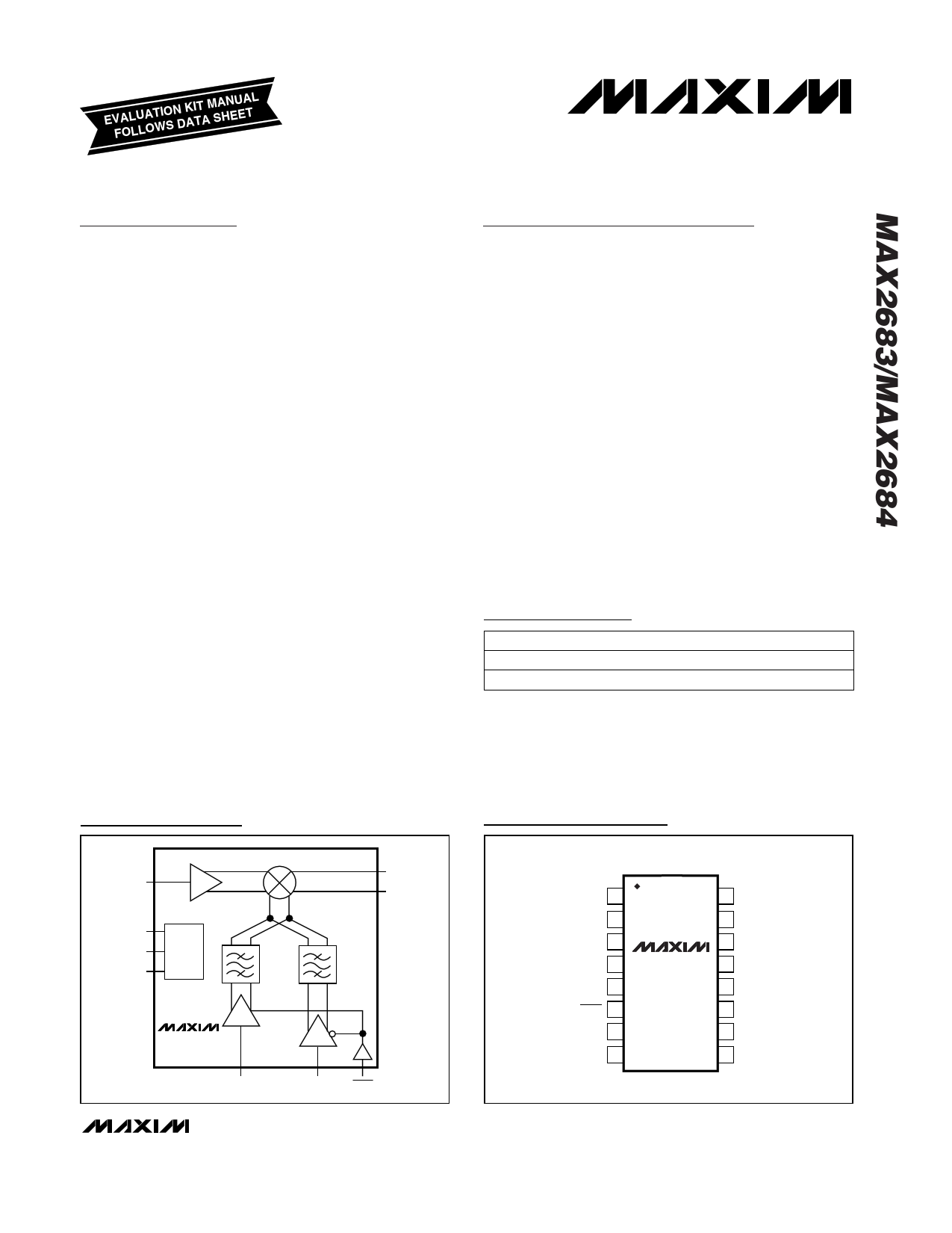
Functional Diagram
IFOUT+
RFIN
IFOUT-
VCC
BIAS BIAS
GND
LO
BUFFER x1
MAX2683
MAX2684
LO
DOUBLER x2
LOX1 LOX2 ENX2
TOP VIEW
Pin Configuration
VCC 1
GND 2
GND 3
RFIN 4
GND 5
ENX2 6
LOX2 7
LOX1 8
MAX2683
MAX2684
16 BIAS
15 GND
14 IFOUT+
13 GND
12 GND
11 IFOUT-
10 GND
9 GND
TSSOP-EP
________________________________________________________________ Maxim Integrated Products 1
For free samples and the latest literature, visit www.maxim-ic.com or phone 1-800-998-8800.
For small orders, phone 1-800-835-8769.
1 page 
3.5GHz Downconverter Mixers
with Selectable LO Doubler
Typical Operating Characteristics (continued)
(MAX2683/MAX2684 EV kit, VCC = +5V, RBIAS = 1.2kΩ, ENX2 = GND, fRF = 3.6GHz, PRF = -20dBm, fLOX2 = 1650MHz for MAX2683 or
fLOX2 = 1350MHz for MAX2684, PLO = -5dBm, all input/output ports terminated in 50Ω, IFOUT+ and IFOUT- matched to single-ended
50Ω load, TA = +25°C, unless otherwise noted.)
MAX2683
CONVERSION GAIN vs. LO POWER
(ENX2 = GND)
10
8 TA = -40°C
6
CONVERSION GAIN vs. LO POWER
(ENX2 = VCC)
10
8 TA = -40°C
6
NOISE FIGURE vs. LO POWER
30
25
4
2 TA = +25°C
4
2
TA = +25°C
20
0 0 15
-2
-4 TA = +85°C
-2 TA = +85°C
-4
10
-6 -6
-8 -8
5
-10
-20 -15 -10
-5
0
LO POWER (dBm)
CONVERSION GAIN vs. SUPPLY VOLTAGE
(RBIAS = 820Ω)
10
9 TA = -40°C
-10
-20 -15 -10
-5
0
LO POWER (dBm)
CONVERSION GAIN vs. SUPPLY VOLTAGE
(RBIAS = 1.2kΩ)
10
9 TA = -40°C
0
-16 -14 -12 -10 -8 -6 -4 -2 0
LO POWER (dBm)
CONVERSION GAIN vs. SUPPLY VOLTAGE
(RBIAS = 2kΩ)
10
9
8 88
7
6 TA = +25°C
5 TA = +85°C
4
3
7
6
5
4 TA = +85°C
3
TA = +25°C
7 TA = -40°C
6
5
TA = +25°C
4
3 TA = +85°C
2
2
ENX2 = VCC
2
1
1 ENX2 = GND
1
0
2.5 3.0 3.5 4.0 4.5 5.0 5.5
SUPPLY VOLTAGE (V)
0
2.5
3.0 3.5 4.0 4.5 5.0
SUPPLY VOLTAGE (V)
5.5
0
2.5 3.0 3.5 4.0 4.5 5.0 5.5
SUPPLY VOLTAGE (V)
INPUT IP3 vs. SUPPLY VOLTAGE
(RBIAS = 820Ω)
15
INPUT IP3 vs. SUPPLY VOLTAGE
(RBIAS = 1.2kΩ)
10
TA = +85°C
INPUT IP3 vs. SUPPLY VOLTAGE
(RBIAS = 2kΩ)
10
12 9 9
TA = +25°C
9 TA = +25°C
6
3 TA = +85°C
TA = -40°C
8
7
6
TA = -40°C
8
7
TA = +85°C
TA = -40°C
6
0
2.5 3.0 3.5 4.0 4.5 5.0 5.5
SUPPLY VOLTAGE (V)
5
2.5 3.0 3.5 4.0 4.5 5.0 5.5
SUPPLY VOLTAGE (V)
TA = +25°C
5
2.5 3.0 3.5 4.0 4.5 5.0 5.5
SUPPLY VOLTAGE (V)
_______________________________________________________________________________________ 5
5 Page 
3.5GHz Downconverter Mixers
with Selectable LO Doubler
Typical Operating Characteristics (continued)
(MAX2683/MAX2684 EV kit, VCC = +5V, RBIAS = 1.2kΩ, ENX2 = GND, fRF = 3.6GHz, PRF = -20dBm, fLOX2 = 1650MHz for MAX2683 or
fLOX2 = 1350MHz for MAX2684, PLO = -5dBm, all input/output ports terminated in 50Ω, IFOUT+ and IFOUT- matched to single-ended
50Ω load, TA = +25°C, unless otherwise noted.)
MAX2684
IF PORT S11 vs. RBIAS
RFIN S11 vs. RBIAS
1.2kΩ,
2kΩ, 820kΩ
2kΩ,
1.2kΩ, 820kΩ
PIN
1
2, 3, 5, 9,
10, 12, 13,
15, EP
4
6
7
8
11, 14
16
NAME
VCC
GND
RFIN
ENX2
LOX2
LOX1
IFOUT-,
IFOUT+
BIAS
Pin Description
FUNCTION
Supply Voltage Input. Bypass with a 100pF capacitor as close to the pin as possible.
Ground. Connect to ground plane with a low-inductance connection. Solder exposed paddle
evenly to the board ground plane.
RF Input Port to Mixer. Requires a matching network and a DC-blocking capacitor that may be part
of this network.
LO Frequency-Doubler Enable Input. Drive low to enable the LO doubler and run external LO at
half frequency. Drive high to disable the LO doubler and run external LO at full frequency.
Half-Frequency Local-Oscillator Input to LO Frequency Doubler, LO Filter, and Downconverter
Mixer. Requires a DC-blocking capacitor. Leave unconnected if this pin is not used.
Full-Frequency Local-Oscillator Input to Downconverter Mixer. Requires a DC-blocking capacitor.
Leave unconnected if this pin is not used.
Differential, Open-Collector IF Output Ports of Mixer. Requires a matching network and pull-up
inductors to VCC that can be part of this network.
Bias-Setting Resistor Connection. A resistor, RBIAS, placed from BIAS to GND sets the linearity and
supply current of the mixer.
______________________________________________________________________________________ 11
11 Page | ||
| Páginas | Total 18 Páginas | |
| PDF Descargar | [ Datasheet MAX2683.PDF ] | |
Hoja de datos destacado
| Número de pieza | Descripción | Fabricantes |
| MAX268 | Pin Programmable Universal and Bandpass Filters | Maxim Integrated |
| MAX2680 | 400MHz to 2.5GHz / Low-Noise / SiGe Downconverter Mixers | Maxim Integrated |
| MAX2682 | 400MHz to 2.5GHz / Low-Noise / SiGe Downconverter Mixers | Maxim Integrated |
| MAX2683 | 3.5GHz Downconverter Mixers with Selectable LO Doubler | Maxim Integrated |
| Número de pieza | Descripción | Fabricantes |
| SLA6805M | High Voltage 3 phase Motor Driver IC. |
Sanken |
| SDC1742 | 12- and 14-Bit Hybrid Synchro / Resolver-to-Digital Converters. |
Analog Devices |
|
DataSheet.es es una pagina web que funciona como un repositorio de manuales o hoja de datos de muchos de los productos más populares, |
| DataSheet.es | 2020 | Privacy Policy | Contacto | Buscar |