|
|
|
PDF MAX1661 Data sheet ( Hoja de datos )
| Número de pieza | MAX1661 | |
| Descripción | Serial-to-Parallel/Parallel-to-Serial Converters and Load-Switch Controllers with SMBus Interface | |
| Fabricantes | Maxim Integrated | |
| Logotipo | ||
Hay una vista previa y un enlace de descarga de MAX1661 (archivo pdf) en la parte inferior de esta página. Total 16 Páginas | ||
|
No Preview Available !
19-1356; Rev 0; 4/98
Active-Matrix Liquid Crystal Display
(AMLCD) Supply
________________General Description
The MAX1664 integrates power-supply and backplane
drive circuitry for active-matrix thin-film-transistor (TFT) liq-
uid crystal displays. Included are a single-output, pulse-
width-modulation boost converter (0.25Ω switch), a
dual-output (positive and negative) gate-driver supply
using one inductor, an LCD backplane driver, and a sim-
ple phase-locked loop to synchronize all three outputs.
High switching frequency (1MHz nominal) and phase-
locked operation allow the use of small, minimum-
height external components while maintaining low
output noise. A +2.8V to +5.5V input voltage range
allows operation with any logic supply. Output voltages
are adjustable to +5.5V (DC-DC 1) and to +28V and
-10V (DC-DC 2). The negative output voltage can be
adjusted to -20V with additional components. Also
included are a logic-level shutdown and a “Ready” out-
put (RDY) that signals when all three outputs are in reg-
ulation.
The boost-converter operating frequency can be set at
16, 24, or 32 times the backplane clock. This flexibility
allows a high DC-DC converter frequency to be used
with LCD backplane clock rates ranging from 20kHz to
72kHz. The MAX1664 is supplied in a 1.1mm-high
TSSOP package.
________________________Applications
LCD Modules
LCD Panels
___________________Pin Configuration
TOP VIEW
SHDN 1
RDY 2
FB1 3
REF 4
GND 5
IN 6
FB2- 7
FB2+ 8
PLLC 9
BPVSS 10
MAX1664
TSSOP
20 FPLL
19 LX1
18 PGND1
17 PGND2
16 LX2N
15 LX2P
14 INP
13 BPCLK
12 BPVDD
11 BPDRV
____________________________Features
o Integrates All Active Circuitry for Three DC-DC
Converters
o Ultra-Small External Components
(ceramic capacitors, 2µH to 5µH inductors)
o DC-DC Converters Phase-Locked to Backplane
Frequency for Lowest Noise
o Low Operating Voltage (down to +2.8V)
o Adjustable Output Voltage from VIN to +5.5V
o Load Currents Up to 500mA
o Adjustable TFT Gate Driver Output:
Positive, VIN to +28V
Negative, 0 to -10V (-20V with added
components)
o Includes 0.35Ω Backplane Driver
o 1µA Shutdown Current
o Power-Ready Output Signal
_______________Ordering Information
PART
MAX1664CUP
TEMP. RANGE
0°C to +70°C
PIN-PACKAGE
20 TSSOP
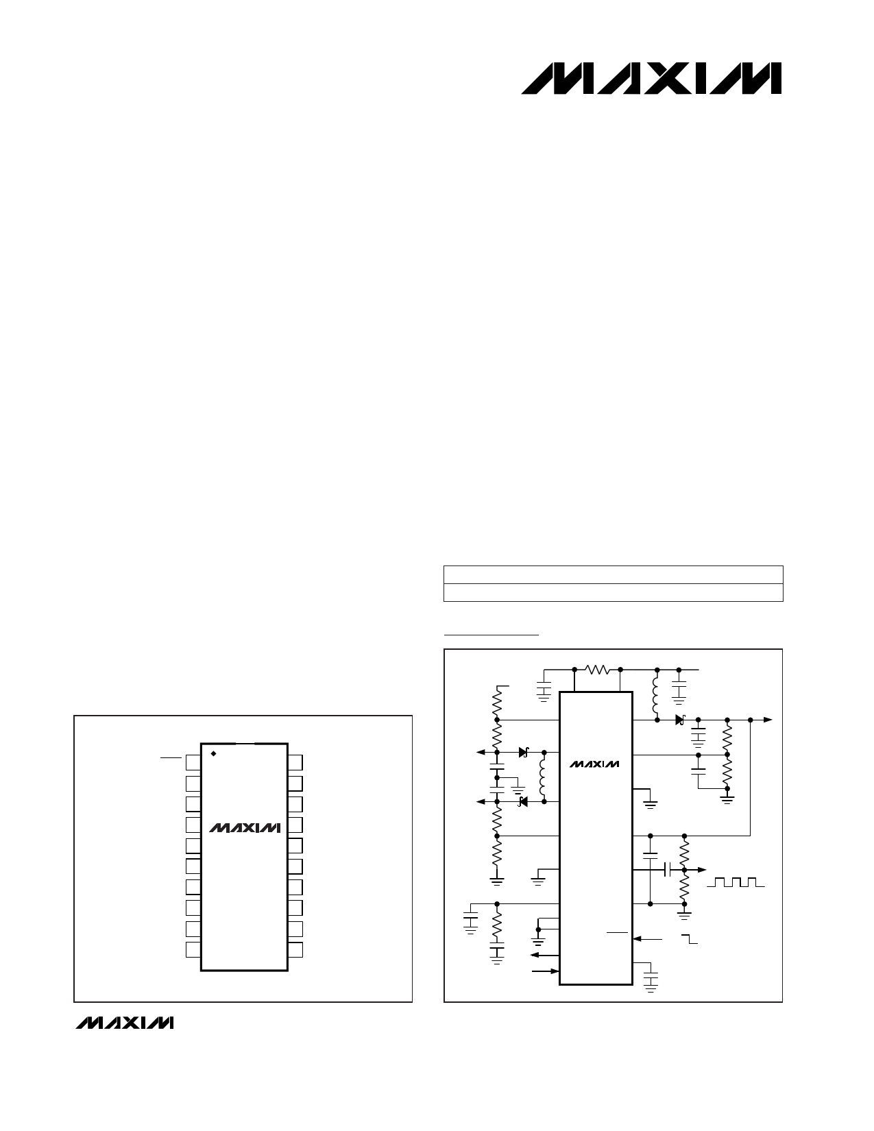
Typical Operating Circuit
REF
IN INP
FB2- LX1
-10V LX2P FB1
MAX1664
PGND1
28V LX2N
VSUPPLY
2.8V TO 5.5V
5.5V
FB2+ BPVDD
PGND2 BPDRV
BACKPLANE
DRIVER
PLLC
GND
FPLL
RDY
BPCLK
BPVSS
SHDN
REF
ON
OFF
________________________________________________________________ Maxim Integrated Products 1
For free samples & the latest literature: http://www.maxim-ic.com, or phone 1-800-998-8800.
For small orders, phone 408-737-7600 ext. 3468.
1 page 
Active-Matrix Liquid Crystal Display
(AMLCD) Supply
Typical Operating Characteristics (continued)
(fBPCLK = 22.5kHz, FPLL = GND, L1 = 3.3µH, L2 = 4.7µH, TA = +25°C, unless otherwise noted.)
VOUT1 LINE-TRANSIENT RESPONSE
VOUT2+ LINE-TRANSIENT RESPONSE
A 50mV/
div
B 500mV/
div
2ms/div
VOUT1 = 5V, ILOAD = 250mA, COUT1 = 20µF
A: VOUT1, 50mV/div, AC COUPLED
B: VIN, 3V to 4V
VOUT2- LINE-TRANSIENT RESPONSE
200mV/
A div
A 200mV/
div
B 500mV/
div
2ms/div
VOUT2+ = 15V, ILOAD = 5mA, COUT2+ = 0.22µF
A: VOUT2+, 200mV/div, AC COUPLED
B: VIN, 3V to 4V
VOUT1 LOAD-TRANSIENT RESPONSE
A
50mV/
div
B
500mV/
div
B
100mA/
div
2ms/div
VOUT2- = -5V, ILOAD = 5mA, COUT2- = 0.47µF
A: VOUT2-, 200mV/div, AC COUPLED
B: VIN, 3V to 4V
INTERNAL FET ON-RESISTANCE
vs. TEMPERATURE
1400
1200 LX2N
1000
800
BPDRV P-CHANNEL LX2P
600
400 BPDRV N-CHANNEL
200
LX1
0
0 10 20 30 40 50 60 70 80 90
TEMPERATURE (°C)
2ms/div
VOUT1 = 5V, VIN = 3.3V, COUT1 = 20µF
A: VOUT1, 50mV/div, AC COUPLED
B: IOUT1, 25mA TO 225mA, 100mA/div
BPDRV RISE AND FALL TIME
vs. LOAD CAPACITANCE
300
250
200
RISE TIME
150
100
50
0
0.001
FALL TIME
CLOAD FROM
BPDRV TO GND
0.01 0.1
LOAD CAPACITANCE (µF)
1
_______________________________________________________________________________________ 5
5 Page 
Active-Matrix Liquid Crystal Display
(AMLCD) Supply
VOUT2-
-5V
0.47µF
0.22µF
VOUT2+
15V
33Ω
REF 0.47µF
R5
49.9k IN INP
FB2- LX1
R6
200k
D2
L2
4.7µH
LX2P FB1
MAX1664
PGND1
LX2N
R7 D3
549k
FB2+ BPVDD
R8
49.9k
PGND2
BPDRV
2.2nF
100k
22nF
PLLC
BPCLK
RDY
GND
FPLL
BPVSS
SHDN
REF
2.2µF 10µF
3.3µH
VSUPPLY
2.8V TO 5.5V
2.2µF
3 x 10µF
50pF
R1
301k
R2
100k
10µF
2 x 10µF
R3
100k
BACKPLANE
DRIVER
R4
100k
ON
OFF
0.22µF
VOUT1
5.5V
Figure 4. Detailed Typical Operating Circuit
Inductor Selection
The optimum inductor value for L1 is 3.3µH, as shown
in Figure 4. Inductors with less than 300mΩ DC series
resistance are recommended to achieve the highest
efficiency. Using a larger value for L1 (e.g., 4.7µH)
increases the output current capability of DC-DC 1 (by
reducing the peak ripple current) at the expense of size
and the additional output filter capacitance needed for
loop stability.
For DC-DC 2, at large input voltages (i.e., 5V) and low
switching frequencies (i.e., ≤400kHz), the value of L2
should be increased (e.g., 6.8µH or 10µH) to limit the
peak current. In some cases it may be necessary to
reduce the value of L2 to increase the output current
capability of DC-DC 2 (Table 2). The relationship between
input voltage, output voltage, switching frequency, induc-
tor value, and maximum load current for DC-DC 2 is com-
plex and nonlinear. This relationship is summarized in
Table 2. The L2 equation is as follows:
[ ]VINP - RON(LX2P) + RON(LX2N) + RL2
L2 >
( )IPEAK x 2 fDC-DC 1
(IPEAK )
2
where:
Internal MOSFET on-resistance:
RON(LX2P) = RON(LX2N) = 0.9Ω typical
External inductor DC resistance:
RL2 = 0.3Ω typical
Inductor peak current:
IPEAK = 700mA (750mA absolute maximum)
Due to the MAX1664’s high switching frequency, induc-
tors with a high-frequency core material such as ferrite
are recommended. Powdered iron compounds are not
recommended due to their higher core losses. Typical
small-size, low-profile inductors include the ILS-3825
(Dale Electronics-Vishay) and the CLQ61B (Sumida).
These inductors are primarily used for DC-DC
converters with low height requirements. See Table 3
for more information on manufacturers who provide
low-profile inductors.
______________________________________________________________________________________ 11
11 Page | ||
| Páginas | Total 16 Páginas | |
| PDF Descargar | [ Datasheet MAX1661.PDF ] | |
Hoja de datos destacado
| Número de pieza | Descripción | Fabricantes |
| MAX166 | CMOS P-Compatible / 5s / 8-Bit ADCs | Maxim Integrated |
| MAX1660 | Digitally Controlled Fuel-Gauge Interface | Maxim Integrated |
| MAX1660EEE | Digitally Controlled Fuel-Gauge Interface | Maxim Integrated |
| MAX1661 | Active-Matrix Liquid Crystal Display AMLCD Supply | Maxim Integrated |
| Número de pieza | Descripción | Fabricantes |
| SLA6805M | High Voltage 3 phase Motor Driver IC. |
Sanken |
| SDC1742 | 12- and 14-Bit Hybrid Synchro / Resolver-to-Digital Converters. |
Analog Devices |
|
DataSheet.es es una pagina web que funciona como un repositorio de manuales o hoja de datos de muchos de los productos más populares, |
| DataSheet.es | 2020 | Privacy Policy | Contacto | Buscar |