|
|
|
PDF MAX1618 Data sheet ( Hoja de datos )
| Número de pieza | MAX1618 | |
| Descripción | Remote Temperature Sensor with SMBus Serial Interface | |
| Fabricantes | Maxim Integrated | |
| Logotipo | ||
Hay una vista previa y un enlace de descarga de MAX1618 (archivo pdf) en la parte inferior de esta página. Total 20 Páginas | ||
|
No Preview Available !
19-1495; Rev 1; 10/99
Remote Temperature Sensor
with SMBus Serial Interface
________________General Description
The MAX1618 precise digital thermometer reports the
temperature of a remote sensor. The remote sensor is a
diode-connected transistor—typically a low-cost, easily
mounted 2N3904 NPN type—that replaces conventional
thermistors or thermocouples. Remote accuracy is ±3°C
for multiple transistor manufacturers, with no calibration
needed. The MAX1618 can also measure the die temper-
ature of other ICs, such as microprocessors, that contain
an on-chip, diode-connected transistor.
The 2-wire serial interface accepts standard System
Management Bus (SMBus™) Write Byte, Read Byte, Send
Byte, and Receive Byte commands to program the alarm
thresholds and to read temperature data. The data format
is 7 bits plus sign, with each bit corresponding to 1°C, in
two’s complement format. Measurements can be done
automatically and autonomously, with the 16Hz conversion
rate or programmed to operate in a single-shot mode.
The thermostat mode configures the ALERT output as an
interrupt or as a temperature reset that remains active only
while the temperature is above the maximum temperature
limit or below the minimum temperature limit. The ALERT
output polarity in thermostat mode can be configured for
active high or active low. Fan control is implemented using
this ALERT output.
The MAX1618 is available in a small (1.1mm high) 10-pin
µMAX package.
________________________Applications
Desktop and Notebook
Computers
Central Office
Telecom Equipment
Smart Battery Packs
Test and Measurement
LAN Servers
Multichip Modules
Industrial Controls
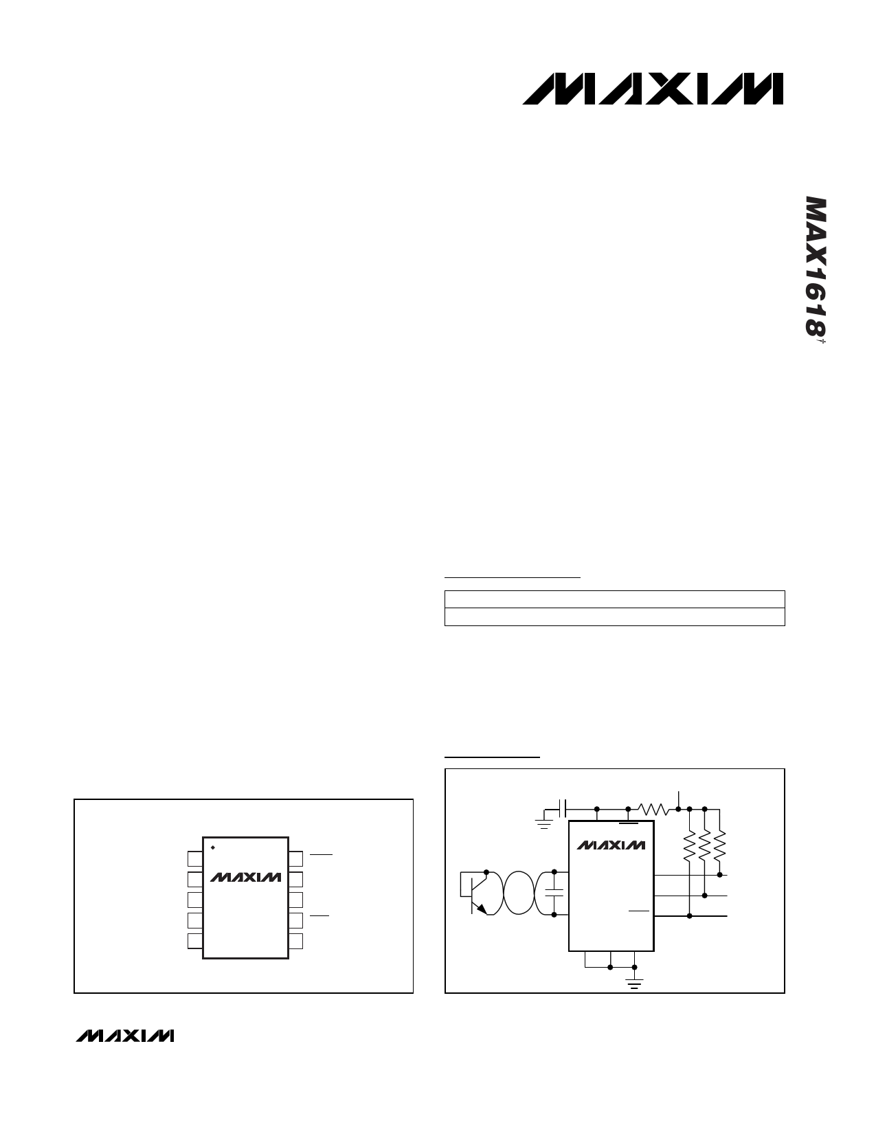
___________________Pin Configuration
TOP VIEW
ADD0 1
ADD1 2
GND 3
DXN 4
DXP 5
MAX1618
µMAX
10 ALERT
9 SMBDATA
8 SMBCLK
7 STBY
6 VCC
____________________________Features
o Single Channel: Measures Remote CPU
Temperature
o No Calibration Required
o SMBus 2-Wire Serial Interface
o Programmable Under/Overtemperature Alarms
o Overtemperature Output for Fan Control
(Thermostat Mode)
o Supports SMBus Alert Response Accuracy
±3°C (+60°C to +100°C)
±5°C (-55°C to +120°C)
o 3µA (typ) Standby Supply Current
o 900µA (max) Supply Current in Autoconvert Mode
o +3V to +5.5V Supply Range
o Small 10-Pin µMAX Package
PART
MAX1618MUB
Ordering Information
TEMP. RANGE
-55°C to +125°C
PIN-PACKAGE
10 µMAX
2N3904
Typical Operating Circuit
0.1µF
3V TO 5.5V
200Ω
VCC STBY
MAX1618
DXP SMBCLK
SMBDATA
DXN
2200pF
ALERT
ADD0 ADD1 GND
10k EACH
CLOCK
DATA
INTERRUPT
TO µC
SMBus is a trademark of Intel Corp.
†Patents Pending
________________________________________________________________ Maxim Integrated Products 1
For free samples & the latest literature: http://www.maxim-ic.com, or phone 1-800-998-8800.
For small orders, phone 1-800-835-8769.
1 page 
Remote Temperature Sensor
with SMBus Serial Interface
____________________________Typical Operating Characteristics (continued)
(TA = +25°C, unless otherwise noted.)
TEMPERATURE ERROR vs.
COMMON-MODE NOISE FREQUENCY
120 AC-COUPLED TO DXN
2200pF DXN-DXP CAPACITOR
100
VIN = 100mVp-p
80
TEMPERATURE ERROR
vs. DXP-DXN CAPACITANCE
0
VCC = 5V
60 -10
40
VIN = 50mVp-p
20
0
10 100 1000
COMMON-MODE NOISE FREQUENCY (MHz)
-20
0
STANDBY SUPPLY CURRENT
vs. CLOCK FREQUENCY
50
20 40 60 80
DXP-DXN CAPACITANCE (nF)
100
40
30
VCC = 5V
20
VCC = 3.3V
10
0
1
100
90
80
70
60
50
40
30
20
10
0
0
STANDBY SUPPLY CURRENT
vs. SUPPLY VOLTAGE
ADD0, ADD1 = GND
ADD0, ADD1 = HIGH-Z
1234
SUPPLY VOLTAGE (V)
5
10 100
CLOCK FREQUENCY (kHz)
1000
RESPONSE TO THERMAL SHOCK
120
110
100
90
80
70
60
50
40
30 10-PIN µMAX IMMERSED IN
+115°C FLUORINERT BATH
20
-2 0 2 4 6 8 10 12 14 16 18 20
TIME (sec)
_______________________________________________________________________________________ 5
5 Page 
Remote Temperature Sensor
with SMBus Serial Interface
Table 3. Command-Byte Bit Assignments
REGISTER
COMMAND
POR STATE
FUNCTION
RFU 00h
N/A Reserved for future use
RRTE
01h
0000 0000*
Read remote temperature; returns latest temperature
RSL 02h
N/A Read status byte (flags, busy signal)
RCL
03h
0000 1000
Read configuration byte
RCRA
04h
0000 0111
Read conversion rate byte (not supported by MAX1618)
RFU 05h
N/A Reserved for future use
RFU 06h
N/A Reserved for future use
RRHI
RRLS
WCA
07h
0111 1111
Read remote THIGH limit
08h
1100 1001
Read remote TLOW limit
09h N/A Write configuration byte
WCRW
0Ah
N/A Write conversion rate byte (not supported by MAX1618)
RFU 0Bh
N/A Reserved for future use
RFU 0Ch
N/A Reserved for future use
WRHA
WRLN
OSHT
0Dh
0Eh
0Fh
N/A Write remote THIGH limit
N/A Write remote TLOW limit
N/A One-shot command
MFGID
FEh
01001101
Read manufacturer ID code
DEVID
FFh
00000010
Read device ID code
*If the device is in hardware standby mode at POR, the temperature register reads 0°C.
Table 4. Configuration-Byte Bit
Assignments
BIT
7
(MSB)
NAME
POR
STATE
MASK
0
FUNCTION
Masks all ALERT interrupts
when high.
Standby mode control bit. If
high, the device immediately
6
RUN/
STOP
0
stops converting and enters
standby mode. If low, the
device converts in either
one-shot or timer mode.
ALERT pin polarity control in
5
POL
0
thermostat mode.
0 = active low
1 = active high
4 THERM 0
Enables thermostat mode
when high.
Enables diode bias current.
0 (Logic Low) = 5µA to 50µA
3 ID 1 (typ)
1 (Logic High) = 10µA to
100µA (typ)
2 to 0 RFU
0 Reserved for future use.
Table 5. Status-Byte Bit
Assignments
BIT NAME
FUNCTION
7
(MSB)
BUSY
A high indicates that the ADC is busy
converting.
6, 5 RFU Reserved for future use (returns 0).
A high indicates that the remote high-
4
RHIGH*
temperature alarm has activated. In
thermostat mode, this bit is always in
the same state as the ALERT output.
A high indicates that the remote low-
3
RLOW*
temperature alarm has activated. In
thermostat mode, this bit is always
zero.
A high indicates a remote-diode fault
2 DIODE (open-circuit, shorted diode, or DXP
short to GND).
1, 0
(LSB)
RFU
Reserved for future use (returns 0).
*In ALERT mode, the HIGH and LOW temperature alarm flags
stay high until cleared by POR or until the status byte register
is read.
______________________________________________________________________________________ 11
11 Page | ||
| Páginas | Total 20 Páginas | |
| PDF Descargar | [ Datasheet MAX1618.PDF ] | |
Hoja de datos destacado
| Número de pieza | Descripción | Fabricantes |
| MAX161 | CMOS 8-Bit 8Channel Data Acquisition System | Maxim Integrated |
| MAX1610 | Digitally Controlled CCFL Backlight Power Supplies | Maxim Integrated |
| MAX1610-MAX1611 | Digitally Controlled CCFL Backlight Power Supplies | Maxim Integrated |
| MAX1610CSE | Digitally Controlled CCFL Backlight Power Supplies | Maxim Integrated |
| Número de pieza | Descripción | Fabricantes |
| SLA6805M | High Voltage 3 phase Motor Driver IC. |
Sanken |
| SDC1742 | 12- and 14-Bit Hybrid Synchro / Resolver-to-Digital Converters. |
Analog Devices |
|
DataSheet.es es una pagina web que funciona como un repositorio de manuales o hoja de datos de muchos de los productos más populares, |
| DataSheet.es | 2020 | Privacy Policy | Contacto | Buscar |