|
|
|
PDF MAX1574 Data sheet ( Hoja de datos )
| Número de pieza | MAX1574 | |
| Descripción | 180mA / 1x/2x / White LED Charge Pump in 3mm x 3mm TDFN | |
| Fabricantes | Maxim Integrated | |
| Logotipo | ||
Hay una vista previa y un enlace de descarga de MAX1574 (archivo pdf) en la parte inferior de esta página. Total 9 Páginas | ||
|
No Preview Available !
19-3117; Rev 0; 12/03
EVAALVUAAILTAIOBNLEKIT
180mA, 1x/2x, White LED Charge Pump
in 3mm x 3mm TDFN
General Description
The MAX1574 charge pump drives up to three white
LEDs with regulated constant current for uniform intensity.
By utilizing adaptive 1x/2x charge-pump modes and
very-low-dropout current regulators, it achieves 180mA
output drive capability and high efficiency over the 1-cell
lithium-battery input voltage range. Fixed-frequency
(1MHz) switching allows for tiny external components,
and the regulation scheme is optimized to ensure low EMI
and low input ripple.
The MAX1574 uses an external resistor to set the full-
scale 100% LED current. An enable input (EN) is used for
simple on/off control or can be pulsed repeatedly to set
lower LED current in multiple steps down to 5%. Once the
desired brightness is set, the MAX1574 maintains con-
stant LED current as long as EN is kept high. If EN is kept
low for more than 2ms, the MAX1574 enters shutdown.
The MAX1574 is available in a 10-pin 3mm x 3mm TDFN
package (0.8mm max height).
Applications
LCD Backlighting
Camera Strobes/Flashes and Movie Lights
Cell Phones/Smart Phones
PDAs, Digital Cameras, and Camcorders
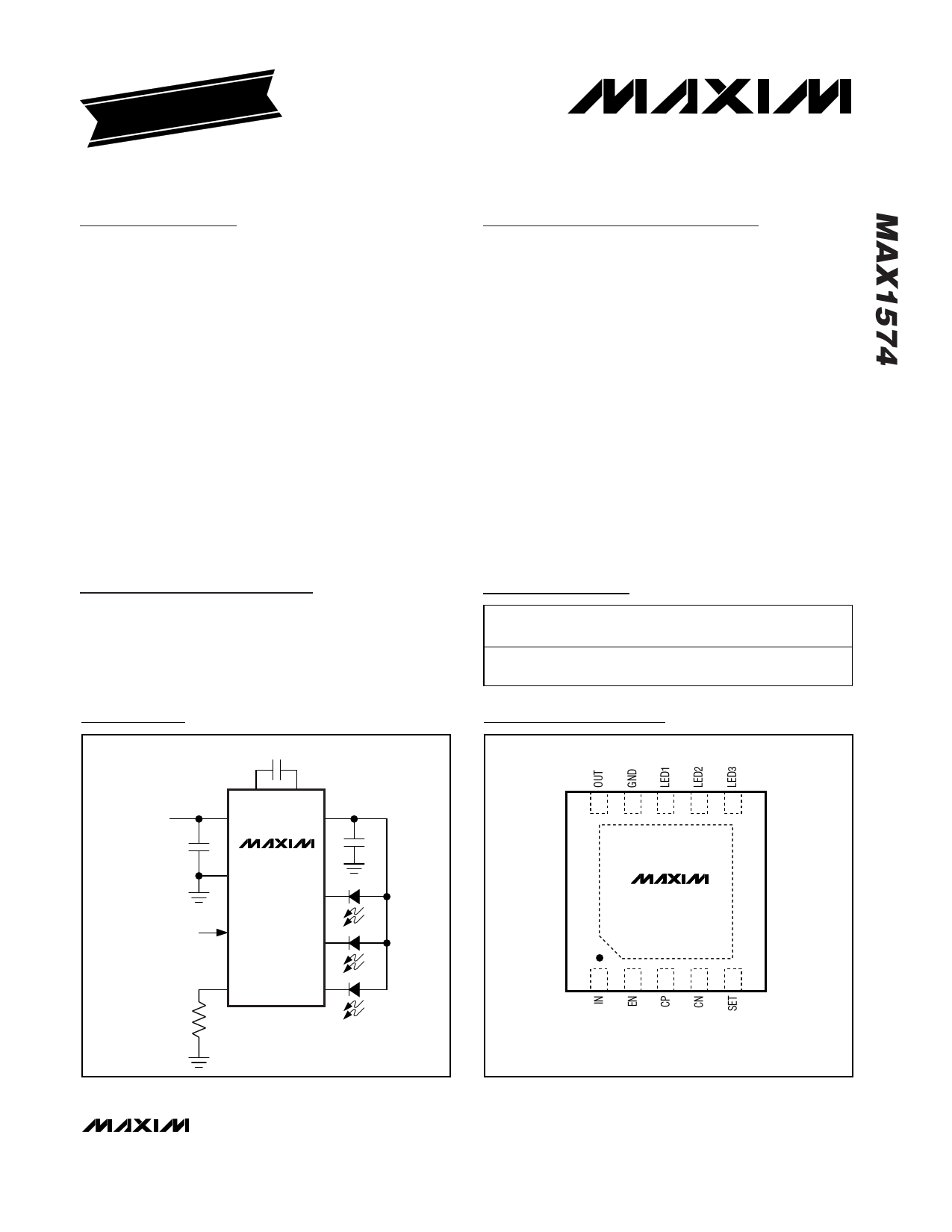
Typical Operating Circuit
0.22µF
2.7V TO 5.5V
CP
IN
CN UP TO 180mA
OUT
1µF
MAX1574
GND
1µF
LED1
ON/OFF AND
DIMMING
EN
LED2
SET LED3
Features
♦ Up to 180mA (60mA/LED) Drive Capability
♦ 83% Average Efficiency (PLED / PBATT) Over Li+
Battery Discharge
♦ 0.5% (typ) LED Current Matching
♦ Adaptive 1x/2x Mode Switchover
♦ Low Input Ripple and EMI
♦ 5% to 100% Dimming Through Single-Wire Serial
Pulse Interface
♦ Low 0.1µA Shutdown Current
♦ 2.7V to 5.5V Supply Voltage Range
♦ Soft-Start Limits Inrush Current
♦ Output Overvoltage Protection
♦ Thermal-Shutdown Protection
♦ 10-Pin 3mm x 3mm TDFN Package
Ordering Information
PART
MAX1574ETB
TEMP RANGE
-40°C to +85°C
PIN-
PACKAGE
10 TDFN
3mm x 3mm
TOP
MARK
ABB
Pin Configuration
TOP VIEW
10 9 8 7 6
MAX1574
123 4 5
TDFN
3mm × 3mm
________________________________________________________________ Maxim Integrated Products 1
For pricing, delivery, and ordering information, please contact Maxim/Dallas Direct! at
1-888-629-4642, or visit Maxim’s website at www.maxim-ic.com.
1 page 
180mA, 1x/2x, White LED Charge Pump
in 3mm x 3mm TDFN
Typical Operating Characteristics (continued)
(Circuit of Figure 2, VIN = 3.6V, EN = IN, driving three white LEDs, TA = +25°C, unless otherwise noted.)
DIMMING RESPONSE
MAX1574 toc10
VEN 2V/div
LINE TRANSIENT 3.8V TO 3.3V TO 3.8V
MAX1574 toc11
VIN 1V/div
VOUT 1V/div
IOUT 50mA/div
VOUT
2V/div
IOUT
60mA,
20mA/div
10ms/div
100µs/div
Pin Description
PIN NAME
FUNCTION
1 IN Supply Voltage Input. Connect a 0.47µF to 1µF ceramic capacitor from IN to GND. The input voltage
range is 2.7V to 5.5V. IN is high impedance during shutdown.
Enable and Dimming Control. Pulsing EN low dims the LEDs in multiple steps. Drive low for longer than
2 EN 2ms (typ) to shut down the IC. From shutdown, drive EN high (50µs min) to set ILED to the maximum
current (see the SETfunction). Pulse EN low for 0.5µs to 500µs to dim the LEDs (Figure 1).
3 CP Transfer-Capacitor Positive Connection. Connect a 0.22µF capacitor from CP to CN.
4 CN Transfer-Capacitor Negative Connection. Connect a 0.22µF capacitor from CP to CN.
5
SET
Current-Set Input. Connect a resistor (RSET) from SET to GND to set the maximum LED current.
ILED(MAX) = 393 × 0.6V / RSET. SET is internally biased to 0.6V. SET is high impedance during shutdown.
6 LED3 LED_ Cathode Connection. Current flowing into LED_ is based on SET description above. In 2x mode,
7 LED2 the charge pump regulates the lowest LED_ voltage to 0.18V. Connect LED_ to IN for unpopulated LEDs.
8 LED1 LED_ is high impedance during shutdown.
9 GND Ground. Connect GND to system ground and as close as possible to the input-bypass capacitor ground.
10
OUT
Output. Connect a 0.47µF to 1µF ceramic capacitor from OUT to GND, and connect OUT to the anodes
of all the LEDs. OUT is pulled to ground through an internal 5kΩ resistor in shutdown.
— EP Exposed Paddle. Connect the exposed paddle directly to GND underneath the IC.
_______________________________________________________________________________________ 5
5 Page | ||
| Páginas | Total 9 Páginas | |
| PDF Descargar | [ Datasheet MAX1574.PDF ] | |
Hoja de datos destacado
| Número de pieza | Descripción | Fabricantes |
| MAX157 | Dual-Channel CardBus and PCMCIA VCC/VPP Power-Switching Networks | Maxim Integrated |
| MAX1570 | White LED Current Regulator with 1x/1.5x High-Efficiency Charge Pump | Maxim Integrated |
| MAX1570ETE | White LED Current Regulator with 1x/1.5x High-Efficiency Charge Pump | Maxim Integrated |
| MAX1572 | PWM DC-to-DC Step-Down Converter | Maxim Integrated Products |
| Número de pieza | Descripción | Fabricantes |
| SLA6805M | High Voltage 3 phase Motor Driver IC. |
Sanken |
| SDC1742 | 12- and 14-Bit Hybrid Synchro / Resolver-to-Digital Converters. |
Analog Devices |
|
DataSheet.es es una pagina web que funciona como un repositorio de manuales o hoja de datos de muchos de los productos más populares, |
| DataSheet.es | 2020 | Privacy Policy | Contacto | Buscar |