|
|
|
PDF M35045 Data sheet ( Hoja de datos )
| Número de pieza | M35045 | |
| Descripción | SCREEN CHARACTER and PATTERN DISPLAY CONTROLLERS | |
| Fabricantes | Mitsubishi | |
| Logotipo | ||
Hay una vista previa y un enlace de descarga de M35045 (archivo pdf) en la parte inferior de esta página. Total 30 Páginas | ||
|
No Preview Available !
MITSUBISHI MICROCOMPUTERS
M35045-XXXSP/FP
SCREEN CHARACTER and PATTERN DISPLAY CONTROLLERS
DESCRIPTION
The M35045-XXXSP/FP is a TV screen display control IC. It uses a
silicon gate CMOS process and is housed in a 20-pin shrink DIP
package (M35045-XXXSP) or a 20-pin shrink SOP package
(M35045-XXXFP).
For M35045-001SP/FP that is a standard ROM version of M35045-
XXXSP/FP respectively, the character pattern is also mentioned.
FEATURES
• Screen composition .................................... 24 columns × 12 lines
• Number of characters displayed ................................... 288 (Max.)
• Character composition ...................................... 12 × 18 dot matrix
• Characters available .............................................. 256 characters
• Character sizes available ..................... 4 (horizontal) × 4 (vertical)
• Display locations available
Horizontal direction .............................................. 1000 locations
Vertical direction .................................................. 1023 locations
• Blinking .................................................................. Character units
Cycle : division of vertical synchronization signal into 64 or 32
Duty : 25%, 50%, or 75%
• Data input .................................. By the 16-bit serial input function
• Coloring
Character color ..................................................... Character unit
Background coloring ............................................. Character unit
Matrix-outline (shadow) coloring .............. 8 colors (RGB output)
Specified by register
Border coloring ......................................... 8 colors (RGB output)
Specified by register
Raster coloring ......................................... 8 colors (RGB output)
• Blanking
Specified by register
Blanking off
Character size blanking
Border size blanking
Matrix-outline blanking
• Output ports
All blanking (all raster area)
4 shared output ports (toggled between RGB output)
4 dedicated output ports
• Display RAM erase function
• Display input frequency range ................... FOSC = 30MHz-80MHz
APPLICATION
Monitor
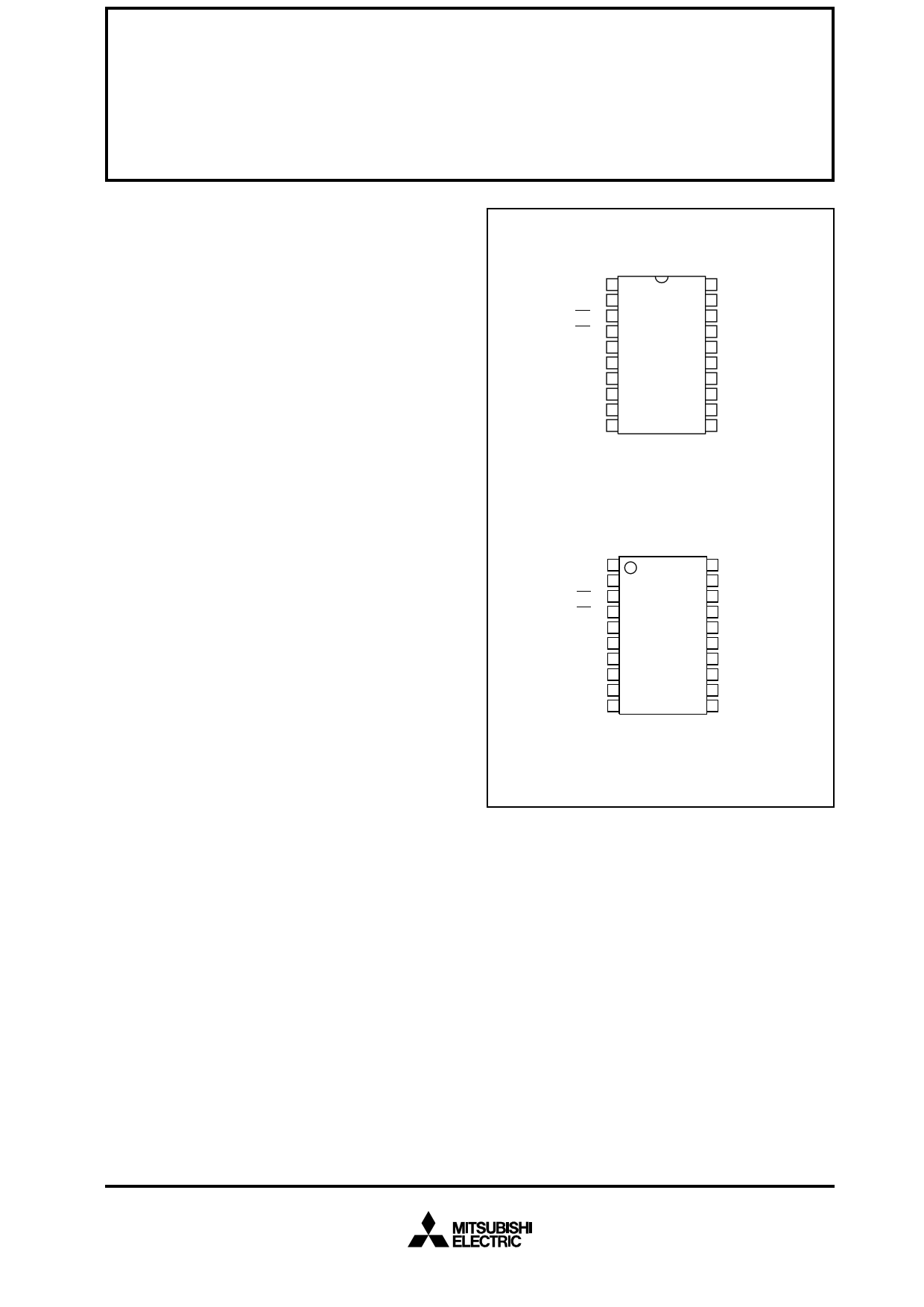
PIN CONFIGURATION (TOP VIEW)
CPOUT ← 1
VIR 2
AC → 3
CS → 4
SCK → 5
SIN → 6
TCK → 7
VDD1 8
P6 ← 9
P7 ← 10
20 VDD2
19 ← VERT
18 ← HOR
17 → P5/B
16 → P4
15 → P3/G
14 → P2
13 → P1/R
12 → P0/BLNK0
11 VSS
Outline 20P4B
CPOUT ← 1
VIR 2
AC → 3
CS → 4
SCK → 5
SIN → 6
TCK → 7
VDD1 8
P6 ← 9
P7 ← 10
20 VDD2
19 ← VERT
18 ← HOR
17 → P5/B
16 → P4
15 → P3/G
14 → P2
13 → P1/R
12 → P0/BLNK0
11 VSS
Outline 20P2Q-A
1 page 
MITSUBISHI MICROCOMPUTERS
M35045-XXXSP/FP
SCREEN CHARACTER and PATTERN DISPLAY CONTROLLERS
REGISTERS DESCRIPTION
(1) Address 12016
DA Register
Status
Contents
Function
Remarks
0 Set multiply value (frequency value) of horizontal synchronous fre- Display frequency is computed as
0 DIV0
quency.
shown below.
1
0
1 DIV1
1
10
0 N1 = Σ (DIVn × 2n)
2 DIV2
n=0
FOSC = fH × N1
FOSC [MHz] : Display frequency
fH [kHz] : Horizontal synchronous
signal frequency to HOR
pin.
N1 : Shown left
1 N1: frequency value
Set display frequency FOSC to within
0
3 DIV3
1
30MHz to 80MHz range.
When display frequency FOSC, set fre-
quency value N2 in association with
DIVS0 and DIVS1.
0
4 DIV4
1
0
5 DIV5
1
0
6 DIV6
1
0
7 DIV7
1
0
8 DIV8
1
0
9 DIV9
1
0
A DIV10
1
0 Set frequency value N2
B DIVS0
1
DIVS
10
Frequency
value N2
0 0 Division into 2
0 0 1 Division into 3
C DIVS1
1 0 Division into 4
1 1 1 Do not set
Set frequency value N2 in association
with display frequency range.
Display frequency
55 ~ 80
40 ~ 55
30 ~ 40
Frequency value N2
Division into 2
Division into 3
Division into 4
0 It should be fixed to “0”.
D DIVS2
1 Can not be used.
__
Note: The mark ⁄ around the status value means the reset status by the “L” level is input to AC pin.
5
5 Page 
MITSUBISHI MICROCOMPUTERS
M35045-XXXSP/FP
SCREEN CHARACTER and PATTERN DISPLAY CONTROLLERS
(7) Address 12616
DA Register
Status
Contents
Function
0 The first line is set by VSZ1L0 and VSZ1L1.
0 LIN10
The second to 12th lines are set by VSZ2L0 and VSZ2L1.
1
The first line is set by VSZ1H0 and VSZ1H1.
The second to 12th lines are set by VSZ2H0 and VSZ2H1.
0 The first line is set by VSZ1L0 and VSZ1L1.
1 LIN11
The second to 12th lines are set by VSZ2L0 and VSZ2L1.
1
The first line is set by VSZ1H0 and VSZ1H1.
The second to 12th lines are set by VSZ2H0 and VSZ2H1.
0 The first line is set by VSZ1L0 and VSZ1L1.
2 LIN12
The second to 12th lines are set by VSZ2L0 and VSZ2L1.
1
The first line is set by VSZ1H0 and VSZ1H1.
The second to 12th lines are set by VSZ2H0 and VSZ2H1.
0 The first line is set by VSZ1L0 and VSZ1L1.
3 LIN13
The second to 12th lines are set by VSZ2L0 and VSZ2L1.
1
The first line is set by VSZ1H0 and VSZ1H1.
The second to 12th lines are set by VSZ2H0 and VSZ2H1.
0 The first line is set by VSZ1L0 and VSZ1L1.
4 LIN14
The second to 12th lines are set by VSZ2L0 and VSZ2L1.
1
The first line is set by VSZ1H0 and VSZ1H1.
The second to 12th lines are set by VSZ2H0 and VSZ2H1.
0 The first line is set by VSZ1L0 and VSZ1L1.
5 LIN15
The second to 12th lines are set by VSZ2L0 and VSZ2L1.
1
The first line is set by VSZ1H0 and VSZ1H1.
The second to 12th lines are set by VSZ2H0 and VSZ2H1.
0 The first line is set by VSZ1L0 and VSZ1L1.
6 LIN16
The second to 12th lines are set by VSZ2L0 and VSZ2L1.
1
The first line is set by VSZ1H0 and VSZ1H1.
The second to 12th lines are set by VSZ2H0 and VSZ2H1.
0 The first line is set by VSZ1L0 and VSZ1L1.
7 LIN17
The second to 12th lines are set by VSZ2L0 and VSZ2L1.
1
The first line is set by VSZ1H0 and VSZ1H1.
The second to 12th lines are set by VSZ2H0 and VSZ2H1.
0 H: Cycle with the horizontal synchronizing pulse
8 V18SZ0
1 V18SZ1 V18SZ0 Vertical direction size
00
1H/dot
0
9 V18SZ1
1
01
10
11
2H/dot
3H/dot
4H/dot
0 H: Cycle with the horizontal synchronizing pulse
A VSZ2L0
1 VSZ2L1 VSZ2L0 Vertical direction size
00
1H/dot
0
B VSZ2L1
1
01
10
11
2H/dot
3H/dot
4H/dot
0 H: Cycle with the horizontal synchronizing pulse
C VSZ2H0
1 VSZ2H1 VSZ2H0 Vertical direction size
00
1H/dot
0
D VSZ2H1
1
01
10
11
2H/dot
3H/dot
4H/dot
Remarks
Character size setting in the vertical
direction for the 10th line.
Character size setting in the vertical
direction for the 11th line.
Character size setting in the vertical
direction for the 12th line.
Character size setting in the vertical
direction for the 13th line.
Character size setting in the vertical
direction for the 14th line.
Character size setting in the vertical
direction for the 15th line.
Character size setting in the vertical
direction for the 16th line.
Character size setting in the vertical
direction for the 17th line.
Character size setting in the vertical
direction for the 18th line.
(display monitor 1 ~ 12 line)
Character size setting in the vertical
direction (display monitor for 2 ~ 12 line)
at “0” state in register LIN2 ~ LIN17.
Character size setting in the vertical
direction (display monitor for 2 ~ 12 line)
at “1” state in register LIN2 ~ LIN17.
11
11 Page | ||
| Páginas | Total 30 Páginas | |
| PDF Descargar | [ Datasheet M35045.PDF ] | |
Hoja de datos destacado
| Número de pieza | Descripción | Fabricantes |
| M35045 | SCREEN CHARACTER and PATTERN DISPLAY CONTROLLERS | Mitsubishi |
| M35046 | SCREEN CHARACTER and PATTERN DISPLAY CONTROLLERS | Mitsubishi |
| M35047 | SCREEN CHARACTER and PATTERN DISPLAY CONTROLLERS | Mitsubishi |
| M35048 | SCREEN CHARACTER and PATTERN DISPLAY CONTROLLERS | Mitsubishi |
| Número de pieza | Descripción | Fabricantes |
| SLA6805M | High Voltage 3 phase Motor Driver IC. |
Sanken |
| SDC1742 | 12- and 14-Bit Hybrid Synchro / Resolver-to-Digital Converters. |
Analog Devices |
|
DataSheet.es es una pagina web que funciona como un repositorio de manuales o hoja de datos de muchos de los productos más populares, |
| DataSheet.es | 2020 | Privacy Policy | Contacto | Buscar |