|
|
|
PDF M66011FP Data sheet ( Hoja de datos )
| Número de pieza | M66011FP | |
| Descripción | SERIAL BUS CONTROLLER | |
| Fabricantes | Mitsubishi | |
| Logotipo | ||
Hay una vista previa y un enlace de descarga de M66011FP (archivo pdf) en la parte inferior de esta página. Total 12 Páginas | ||
|
No Preview Available !
MITMSITUSBUISBHISI H〈DI I〈GDIITGAITLAALSASSPS〉 P〉
M660M16610F11PFP
SESREIARLIABLUBSUCSOCNOTNRTORLOLELRLER
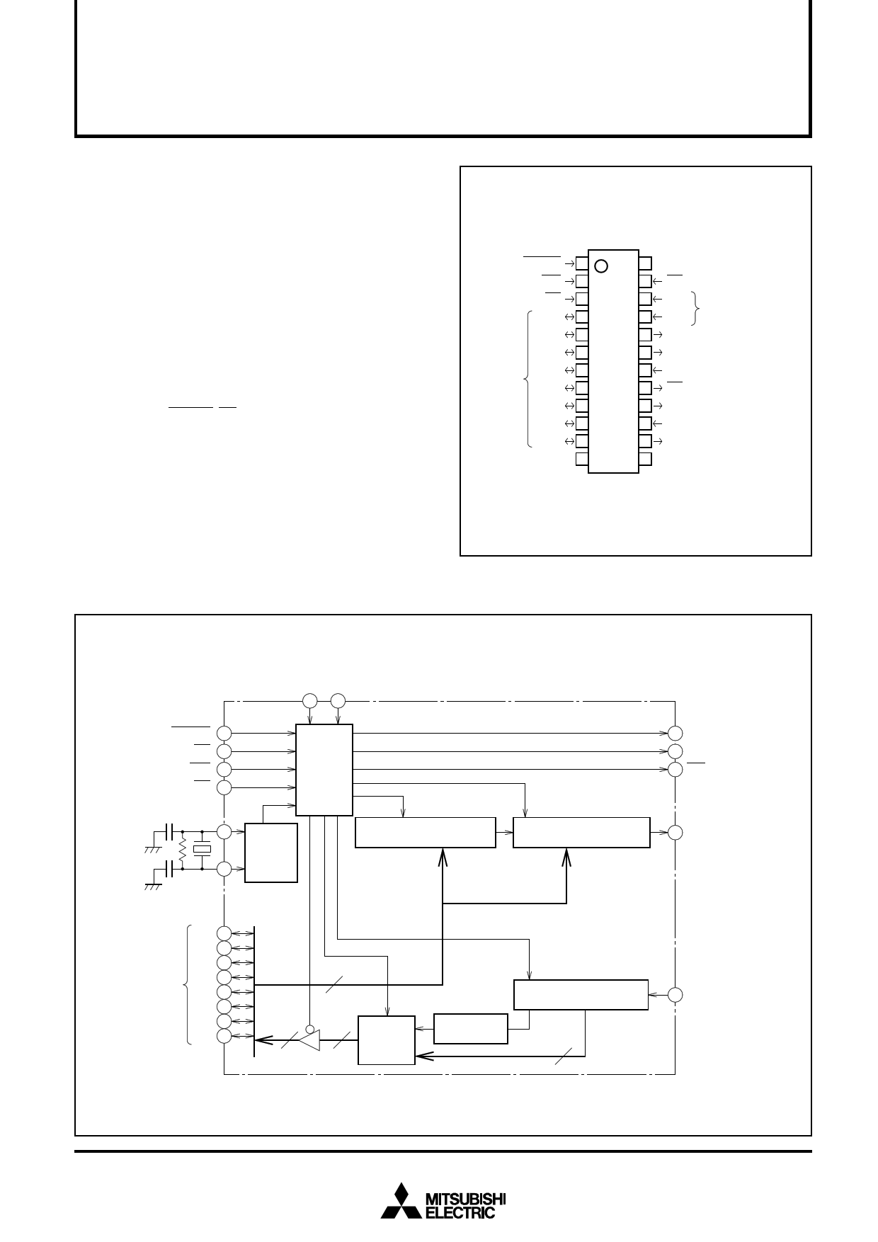
DESCRIPTION
M66011 Semiconductor Integrated Circuit is a serial bus con-
troller. It converts 2-byte parallel data that arrives from micro-
computer into serial and outputs it to serial bus. It also
converts serial data input from serial bus into parallel and out-
puts it to microcomputer.
The M66011 is used for the extension of microcomputer I/O
ports and two-way communication with peripheral equipment
connected with serial buses.
FEATURES
• Compatible with general-purpose 8-bit microprocessor bus-
ses
• TTL level input (one microcomputer side)
• Interrupt output
• Schmitt input (RESET, CS, SIN)
• Low power dissipation
• Wide operating temperature range (Ta = –20 to 75˚C)
APPLICATION
Microcomputer I/O port extension, etc.
PIN CONFIGURATION (TOP VIEW)
RESET INPUT RESET
WRITE INPUT WR
CHIP SELECT
INPUT
CS
D0
D1
D2
DATA BUS
D3
D4
D5
D6
D7
GND
1
2
3
4
5
6
7
8
9
10
11
12
24 VCC
23 RD READ INPUT
22 A0
21 A1
ADDRESS INPUT
20 SCLK SHIFT CLOCK OUTPUT
19 SOUT SERIAL DATA OUTPUT
18 SIN SERIAL DATA INPUT
17 OE OUTPUT ENABLE OUTPUT
16 INT INTERRUPT OUTPUT
15 Xin CLOCK INPUT
14 Xout CLOCK OUTPUT
13 VCC
Outline 24P2N-B
BLOCK DIAGRAM
A1 Af
21 22
RESET INPUT RESET 1
CHIP SELECT INPUT CS 3
WRITE INPUT WR 2
READ INPUT RD 23
CLOCK INPUT
Xin
15
CLOCK OUTPUT
14
Xout
Timing
control
circuit
Oscillation
circuit
CLK, LOAD
Shift register for lower
byte serial output (8 bits)
SRL
CLK, LOAD
Shift register for upper
byte serial output (8 bits)
SRU
SHIFT CLOCK OUTPUT
20 SCLK
16 INT INTERRUPT OUTPUT
17 OE
OUTPUT ENABLE OUTPUT
19 SOUT
SERIAL DATA OUTPUT
DATA BUS
D0 4
D1 5
D2 6
D3 7
D4 8
D5 9
D6 10
D7 11
8
88
X8
Read
register
Acknowledge
bit (ACK)
CLK
Shift register for serial
input (9 bits)
8
18 SIN
SERIAL DATA INPUT
1
1 page 
MITSUBISHI 〈DIGITAL ASSP〉
M66011FP
SERIAL BUS CONTROLLER
3. Serial data input/output operation
A cycle of 16-bit serial output data setting and serial data
communication starts with a write access given by micro-
computer to transmission shift registers in M66011.
M66011 has two 8-bit shift registers, on for upper byte
(SRU), the other for lower byte (SRL). If the CS status rises
from “L” to “H” after a write access is given to SRL, serial
data communication is started. SRU 8-bit data and SRL, 8-
bit data are output in series in this order. Output of each
data starts from its most significant bit.
At the CS rise edge, busy flag in M66011 is set, and OE
output shifts from “H” to “L”. Shift clock SCLK and serial
data SOUT are then output.
At SCLK fall edges, serial output shift register executes
shifting operation, and data on shift register is output in se-
ries from pin SOUT. Serial input data from pin SIN is taken
into input shift register at SCLK 8T thru 16T rise edges.
However, data taken in at 8T rise edge is processed as ac-
knowledge bit, while data taken in at 9T thru 16T rise
edges are processed as data bits.
After the SCLK 16T rise edge, the status of SOUT and OE
shifts to “H” after one bit’s delay of SCLK, and busy flag is
reset. When interrupt output is being set to enable, INT
output is set.
(Remarks)
(1) If CS rises after write operation is executed on SRL only
and not on SRU, SRU data is unstable.
(2) When write operations executed on SRL, M66011 be-
comes ready for start of serial communication and stands
by for detection of CS rise. However, if a read access is
given after data is written on SRL while CS is maintained
on “L” level, this standby status is canceled. To resume se-
rial communication in this case, rewrite data on SRL and
raise CS.
SRL
write operation
CS
Busy flag
(in M66011)
OE
INT
Serial communication period
SCLK
SOUT
SIN
1T 2T
8T 9T
16T
D015 D014 D013 D012 D011 D010 D09 D08 D07 D06 D05 D04 D03 D02 D01 D00
(D7U)
(D0U) (D7L)
(D0L)
ACK DI7 DI6 DI5 DI4 DI3 DI2 DI1 DI0
Serial Communication Timing Chart
5
5 Page 
Operation Flow Chart
Start
Status register set
SRU write
SRL write
CS=“L” to “H”
(Serial communication)
Status read
NO
Busy flag =“0”
YES
NO
Acknowledge =“0”
YES
Serial input data read
MITSUBISHI 〈DIGITAL ASSP〉
M66011FP
SERIAL BUS CONTROLLER
Start
Status register set
SRU write
SRL write
CS=“L” to “H”
(Serial communication start)
(Serial communication end)
Interrupt command output
Status read
NO
Acknowledge =“0”
YES
Serial input data read
Communication trouble
END
When Busy Flag Is Used
Communication trouble
END
When INT Output Is Used
11
11 Page | ||
| Páginas | Total 12 Páginas | |
| PDF Descargar | [ Datasheet M66011FP.PDF ] | |
Hoja de datos destacado
| Número de pieza | Descripción | Fabricantes |
| M66011FP | SERIAL BUS CONTROLLER | Mitsubishi |
| Número de pieza | Descripción | Fabricantes |
| SLA6805M | High Voltage 3 phase Motor Driver IC. |
Sanken |
| SDC1742 | 12- and 14-Bit Hybrid Synchro / Resolver-to-Digital Converters. |
Analog Devices |
|
DataSheet.es es una pagina web que funciona como un repositorio de manuales o hoja de datos de muchos de los productos más populares, |
| DataSheet.es | 2020 | Privacy Policy | Contacto | Buscar |