|
|
|
PDF LA4485 Data sheet ( Hoja de datos )
| Número de pieza | LA4485 | |
| Descripción | 5 W / Two-channel Power Amplifier with Very Few External Parts | |
| Fabricantes | Sanyo | |
| Logotipo | ||
Hay una vista previa y un enlace de descarga de LA4485 (archivo pdf) en la parte inferior de esta página. Total 20 Páginas | ||
|
No Preview Available !
Ordering number: EN3680C
Monolithic Linear IC
LA4485
5 W, Two-channel Power Amplifier with Very Few
External Parts
Overview
The LA4485 is a 5 W, two-channel power amplifier IC that
requires a minimum of external parts, making it ideal for radio
cassette players and car stereo equipment.
The LA4485 eliminates the need for bootstrap capacitors,
negative feedback capacitors, and oscillation prevention CR
parts, all of which were necessities for power ICs previously.
All of these functions are now on chip, keeping the number of
external parts to an absolute minimum. The LA4485 is part of
the Power (Stylish Power) Series, and supports two modes:
dual and BTL.
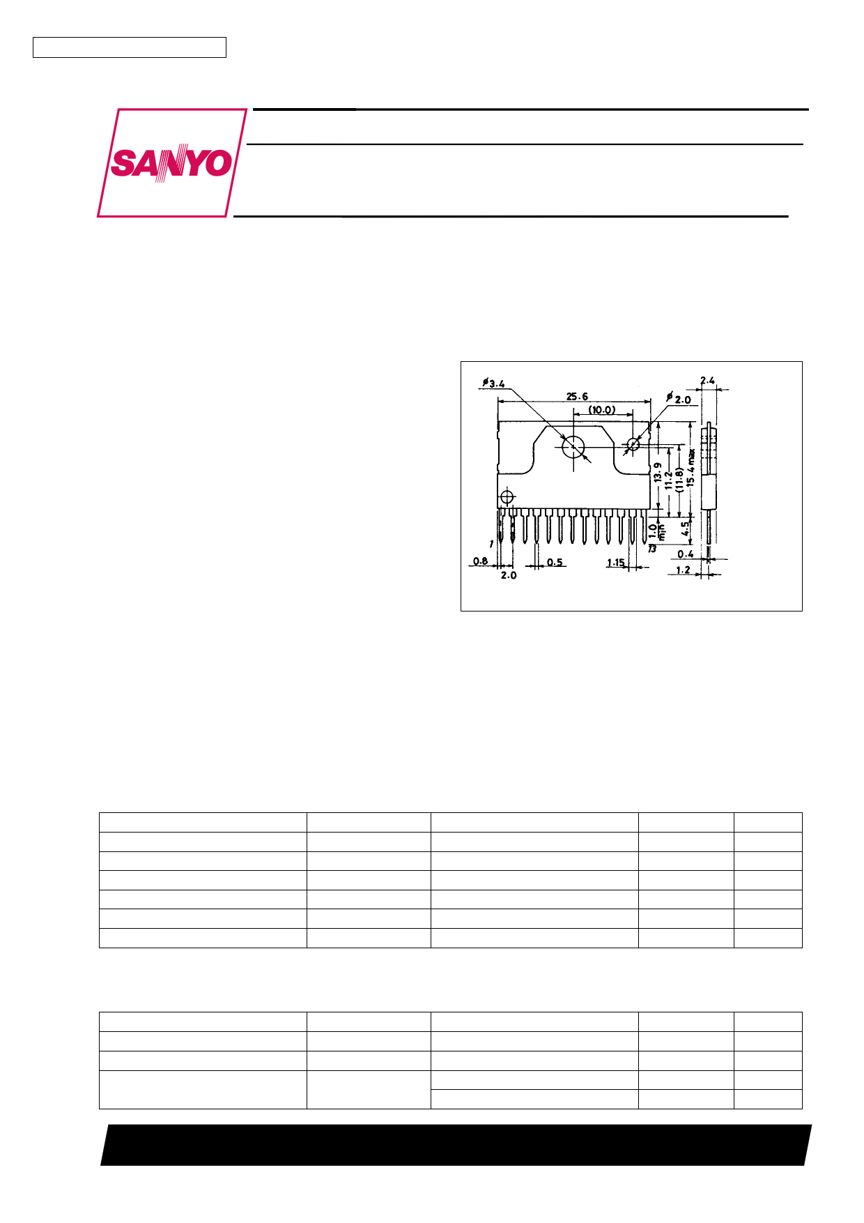
Package Dimensions
unit : mm
3107-SIP13H
[LA4485]
Features
. 5 W × 2 output power in dual mode, and 15 W in BTL mode
. Minimum external parts for the Power Series count:
. 4 or 5 parts in dual mode; 3 or 4 parts in BTL mode
Protection circuits
Overvoltage protection
Thermal protection
DC output short-circuit protection (to VCC and to GND)
. Circuitry designed to handle +VCC applied to the outputs
. Pop noise reduction
. Standby switch
. Muting function
SANYO : SIP13H
Specifications
Maximum Ratings at Ta = 25°C
Parameter
Maximum supply voltage
Surge supply voltage
Peak output current
Allowable power dissipation
Operating temperature
Storage temperature
Symbol
VCC max
VCC surge *
IO peak
Pd max
Topr
Tstg
*: By the π type B check point method.
Operating Conditions at Ta = 25°C
Parameter
Recommended supply voltage
Supply voltage range
Symbol
VCC
VCC op
Recommended load resistance range
RL
Conditions
No signal
Based on the JASO standard
Per channel
With infinite heat sink
Conditions
Must not be over package Pd
Dual
BTL
Ratings
24
50
3.3
15
–30 to +80
–40 to +150
Unit
V
V
A
W
°C
°C
Ratings
13.2
7.5 to 18
2 to 8
4 to 8
Unit
V
V
Ω
Ω
SANYO Electric Co.,Ltd. Semiconductor Bussiness Headquarters
TOKYO OFFICE Tokyo Bldg., 1-10, 1 Chome, Ueno, Taito-ku, TOKYO, 110 JAPAN
73096HA(II)/D2893TS/9041TS No.3680-1/20
1 page 
LA4485
VN – VCC
RL = 4 Ω (dual)
Rg = 0 standby + 5 V
ICCO – VCC
RL = 4 Ω
Rg = 0
Overvoltage cutoff
VCC = 7.5 V
Cutoff for waveform carrying signal
Muting on
Supply voltage, VCC – V
lst – VCC
CVCC = 0.15 µF (mylar)
Rg = 0
Standby to GND
Muting on
ICCO
Supply voltage, VCC – V
PO – VIN
VCC = 13.2 V
RL = 4 Ω
f = 1 kHz
Rg = 600 Ω
Supply voltage, VCC – V
THD – PO
Input voltage, VIN – mV
THD – f
Output power, PO – W
f Response
Frequency, f – Hz
THD – VCC
Frequency, f – Hz
Supply voltage, VCC – V
No.3680-5/20
5 Page 
LA4485
. Insert capacitors of 1000 pF between each input and ground to prevent external noise.
. When the load (RL) or the supply voltage (VCC) is increased, turning the standby switch or the main switch on under strong
input conditions will activate the IC’s internal pseudo ASO protection circuit for the upper power transistor (VCE × ICP). This
causes output oscillations or intermittent operation (The reference area is shown in Figure 1 below). However, strong input tests
after the bias has stabilized have no problems. They also protect the upper power transistors close to the limits of ASO when all
signal switches are on. Therefore, when using this IC under these conditions, the circuit design should obey the following
condition:
Signal generation time > Start-up time of the power amplifier IC
or some other method of attaining the zero-volume condition should be adopted.
. An undervoltage protection circuit operates when the voltage is 7.5 V or lower.
This figure shows the pseudo ASO protection area when strong signal is input, and switch is ON:
the upper power transistors have an area where VCE × ICP load is caused.
PHOTO-2
VCC = 15 V
RL = 3 Ω
PHOTO-1
VCC = 13.2 V
RL = 2 Ω
Strong signal input after switch-ON is OK.
In BTL-mode operation, the load is RL × 2
RL = 4 Ω
Design center
Supply voltage, VCC – V
Figure 1
Dual-mode operation
f = 1 kHz
Dual channel drive
Non-inductive load
Ta = 25°C
Standby switch ON in a
typical application
No.3680-11/20
11 Page | ||
| Páginas | Total 20 Páginas | |
| PDF Descargar | [ Datasheet LA4485.PDF ] | |
Hoja de datos destacado
| Número de pieza | Descripción | Fabricantes |
| LA4485 | 5 W / Two-channel Power Amplifier with Very Few External Parts | Sanyo |
| Número de pieza | Descripción | Fabricantes |
| SLA6805M | High Voltage 3 phase Motor Driver IC. |
Sanken |
| SDC1742 | 12- and 14-Bit Hybrid Synchro / Resolver-to-Digital Converters. |
Analog Devices |
|
DataSheet.es es una pagina web que funciona como un repositorio de manuales o hoja de datos de muchos de los productos más populares, |
| DataSheet.es | 2020 | Privacy Policy | Contacto | Buscar |