|
|
|
PDF TCFGB1A106K8R Data sheet ( Hoja de datos )
| Número de pieza | TCFGB1A106K8R | |
| Descripción | Chip tantalum capacitors with open-function built-in | |
| Fabricantes | ROHM Semiconductor | |
| Logotipo | ||
Hay una vista previa y un enlace de descarga de TCFGB1A106K8R (archivo pdf) en la parte inferior de esta página. Total 15 Páginas | ||
|
No Preview Available !
Tantalum capacitors
Chip tantalum capacitors with
open-function built-in
TCFG series
TCFG series
Semiconductor manufacturing technology has been used to include a temperature fuse in TCFG series capacitors.
These capacitors feature low impedance and are ideal for digital circuits and low-voltage circuits in portable electronic
equipment.
!Features
1) Open-function built into every package.
2) High capacitance in a small package.
3) Low impedance.
4) Use of semiconductor manufacturing technology provides high reliability.
5) Superb solderability.
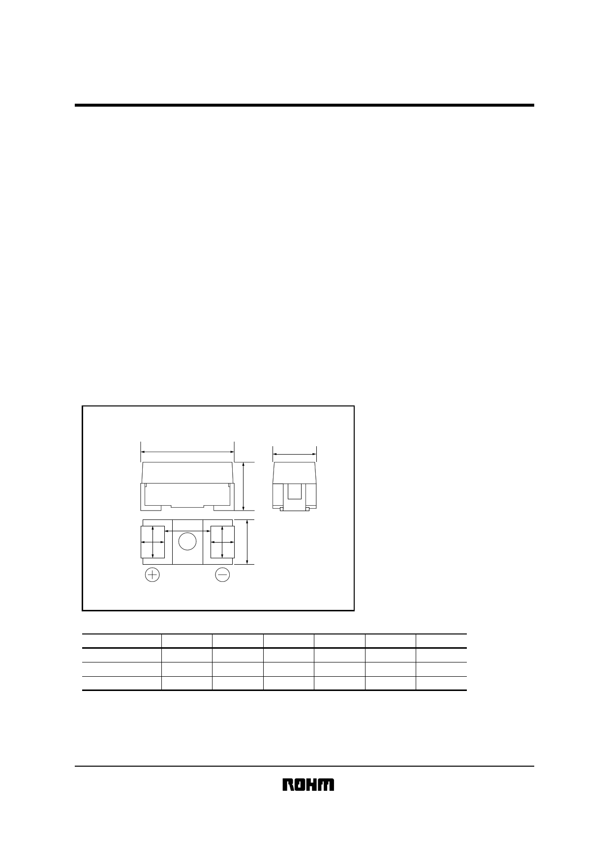
!External dimensions (Units : mm)
L
W1
H
P
S W2
S W2
W1 Max.
Case code
P (2012)
A (3216)
B (3528)
L
2.0 ± 0.2
3.2 ± 0.2
3.5 ± 0.2
W1
1.25 ± 0.2
1.6 ± 0.2
2.8 ± 0.2
W2
0.9 ± 0.2
1.2 ± 0.2
1.9 ± 0.2
H
Max.1.20
1.6 ± 0.2
1.9 ± 0.2
S
0.45 ± 0.3
0.8 ± 0.3
0.8 ± 0.3
P
1.3 ± 0.3
1.6 ± 0.3
1.9 ± 0.3
1 page 
Tantalum capacitors
TCFG series
Item
Performance
Test methods / conditions
(based on JIS C 5102,5143)
Temperature
characteristics
Temperature −55°C
∆C / C
P case within +0% and −15% of the value before testing.
A B case within +10% and −0% of the value before testing.
tanδ P case within 1.5 times of the value before testing.
A B case must satisfy the initial specified value.
L.C −
Temperature +85°C
∆C / C
P case within +0% and −15% of the value before testing.
A B case within +0% and −10% of the value before testing.
tanδ Must satisfy the initial specified value.
L.C Less than or equal to the larger of 5µA or 0.1CV.
Temperature +125°C
∆C / C
P case within +20% and −0% of the value before testing.
A B case within +15% and −0% of the value before testing.
tanδ P case within 1.5 times of the value before testing.
A B case must satisfy the initial specified value.
L.C Less than or equal to the larger of 6.3µA or
0.125CV.
Surge
resistance
Appearance
L.C
∆C / C
A B case no noticeable irregularities, and the
markings must be easy to read.
Must satisfy the initial specified value.
P case within ± 10%
A B case within ± 5%
Apply the rated surge voltage for
30 ± 5s at intervals of 5 ± .05mins.
1000 times, with the temperature at
85 ± 2°C.
High-
temperature
load
Terminal
strength
tanδ
Appearance
L. C
∆C / C
tanδ
Capacitance
Appearance
P case within 1.5 times of the value before testing.
A B case must satisfy the initial specified value.
No noticeable irregularities, and the
markings must be easy to read.
Must satisfy the initial specified value.
Within ± 10%
P case within 1.5 times of the value before testing.
A B case must satisfy the initial specified value.
Value must be stable during measurement.
No noticeable irregularities.
Temp.
: 85 ± 2°C
Series Resistance : 3Ωmax.
Applied voltage : rated voltage
Test time
:
P
case
1000
+36
−0
hrs
A
B
case
2000
+73
−0
hrs
meusure made after pieces shall be left for
1 to 2 hrs under room temp. and room
humidity after test.
Apply pressure to the device using the
specified tool for 5s so that the center
deflection is 1mm (see below).
20
50
(Units: mm)
F (Direction of force)
R230
1
45 45
5 Page 
Tantalum capacitors
TCFG series
(3) Derating voltage as function of temperature
100
90
80
70
60
50
75
85 95 105 115
TEMPERATURE (°C)
125
85°C
Rated Voltage
Surge Voltage
(V.DC)
(V.DC)
4 5.2
6.3 8
10 13
16 20
20 26
Fig.5
125°C
Category Voltage Surge Voltage
(V.DC)
(V.DC)
2.5 3.4
45
6.3 9
10 12
13 16
(4) Reliability
The malfunction rate of tantalum solid state electrolytic capacitors varies considerably depending on the conditions of
usage (ambient temperature, applied voltage, circuit resistance).
Formula for calculating malfunction rate
λp = λb × (πE × πSR × πQ × πCV)
λp : Malfunction rate stemming from operation
λb : Basic malfunction rate
πE : Environmental factors
πSR : Series resistance
πQ : Level of malfunction rate
πCV : Capacitance
For details on how to calculate the malfunction rate stemming from operation, see the tantalum solid state electrolytic
capacitors column in MIL-HDBK-217.
Malfunction rate as function of operating
temperature and rated voltage
1.0
Ratio = Applied Voltage
Rated Voltage
0.5
1.0
0.3
0.2 0.7
0.1
0.06
0.03
0.02
0.5
0.3
0.01
0.1
20 40 60
85
OPERATING TEMPERATURE (°C)
Fig.6
Malfunction rate as function of circuit resistance (Ω/V)
6.0
4.0
2.0
1.0
0.8
0.6
0.4
0.1 0.2 0.4 0.6 1.0 2.0 3.0
RESISTANCE OF CIRCUIT (Ω / V)
Fig.7
11 Page | ||
| Páginas | Total 15 Páginas | |
| PDF Descargar | [ Datasheet TCFGB1A106K8R.PDF ] | |
Hoja de datos destacado
| Número de pieza | Descripción | Fabricantes |
| TCFGB1A106K8R | Chip tantalum capacitors with open-function built-in | ROHM Semiconductor |
| Número de pieza | Descripción | Fabricantes |
| SLA6805M | High Voltage 3 phase Motor Driver IC. |
Sanken |
| SDC1742 | 12- and 14-Bit Hybrid Synchro / Resolver-to-Digital Converters. |
Analog Devices |
|
DataSheet.es es una pagina web que funciona como un repositorio de manuales o hoja de datos de muchos de los productos más populares, |
| DataSheet.es | 2020 | Privacy Policy | Contacto | Buscar |