|
|
|
PDF W3030 Data sheet ( Hoja de datos )
| Número de pieza | W3030 | |
| Descripción | W3030 3 V Dual-Mode IF Cellular Receiver | |
| Fabricantes | Agere Systems | |
| Logotipo | ||
Hay una vista previa y un enlace de descarga de W3030 (archivo pdf) en la parte inferior de esta página. Total 22 Páginas | ||
|
No Preview Available !
Data Sheet
April 1999
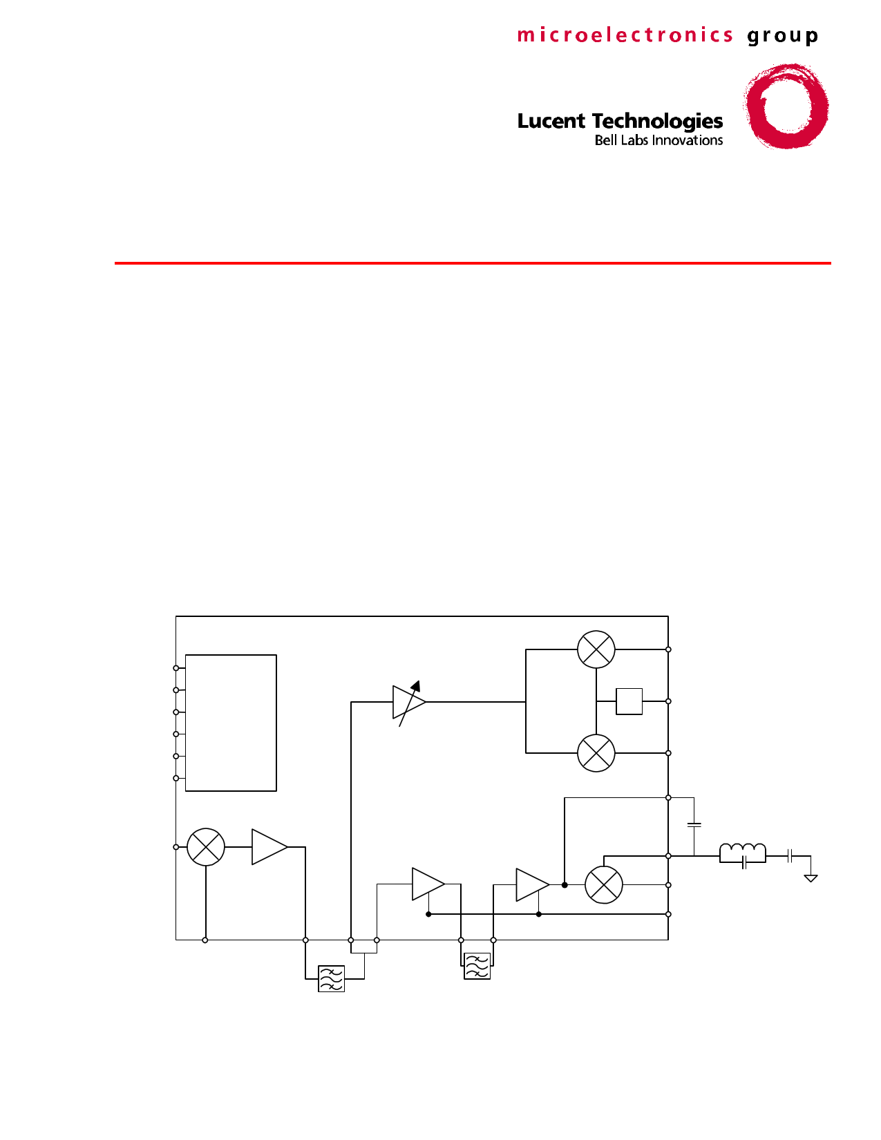
W3030 3 V Dual-Mode IF Cellular Receiver
Features
n Proven double conversion architecture:
First IF capability: 10 MHz to over 1000
MHz
Second IF capability: 0.2 MHz to 2.0 MHz
n Dual second IF amplifiers and demodulators:
Analog-mode limiting amplifier and FM
quadrature detector
Digital-mode linear AGC amplifiers with
dual-mixer I & Q quadrature demodulator
n Accurate, onboard local oscillator phase splitter
for digital quadrature demodulator
n Four enable/powerdown modes, selectable from
two digital control pins, allow operation with
minimal supply current
n Low supply current
n Analog received signal strength indicator (RSSI)
available
n Analog AGC for digital-mode IF amplifiers
n Over 100 dB combined voltage gain
Applications
n IS-136 (North American dual-mode) cellular
radio portable and mobile terminals
n Cellular radio base stations
n Digital satellite communications
n Multisymbol signaling receivers
VCC
GND
ENBA
ENBD
VCM
AGC
LOGIC AND
BIAS
CONTROL
IF INPUT
LO
DIGITAL SECTION
VARIABLE GAIN
ANALOG SECTION
I
÷4 CLK
Q
AUDIO
RSSI
Figure 1. General Block Diagram
1 page 
Data Sheet
April 1999
W3030 3 V Dual-Mode IF Cellular Receiver
Pin Information
Table 1. Pin Descriptions
Pin
Number
1
Pin Name
RSSI
2 AUDIO
3 QUAD
4 IFAOUT
5 IFAACG
6 IFAIN
7 IFA IN
8 VCC2
9 IF2OUT
10 IF2ACG
11 IF2IN
12 IF2 IN
13 GND1
14 IF1OUT
15 IF1 LO
16 IF1LO
17 VCC1
18 IF1 IN
19 IF1IN
Pin Description
Received Signal Strength Indicator. Provides logarithmic (dB-linear) dc output
voltage.
Audio Output. Audio output of FM detector.
Quad Input. Input to FM detector from parallel LC quad coil.
Analog Output. Output of analog section limiting amplifiers; couple to quad coil
and pin 3 (QUAD) with 10 pF capacitor.
Analog Signal Ground. Signal ground for analog section limiting amplifier;
connect to ground with 0.1 µF capacitor.
Analog Mode Limiter Input. Differential input to analog IF limiting amplifier; to
be directly coupled to dielectric sources such as ceramic filters. Pin 6 is
approximately 1 kΩ with pin 5 ac-grounded.
Analog Mode Limiter Input (Inverting). Differential input to analog IF limiting
amplifier. To be ac-grounded.
Second IF Power Supply. Positive power supply connection for both analog
and digital second IF amplifiers and demodulators.
Second IF Output. Output of 40 dB second IF amplifier; directly couple to
dielectric loads such as ceramic filters. Includes internal 1 kΩ termination
resistor.
Second IF Signal Ground. Signal ground for 40 dB second IF amplifier;
connect to ground with 0.1 µF capacitor.
Second IF Input. Differential input to 40 dB second IF amplifier; to be directly
coupled to dielectric sources such as ceramic filters. Pin 11 is approximately
2 kΩ with pin 10 ac-grounded.
Second IF Input (Inverting). Differential input to 40 dB second IF amplifier. To
be ac-grounded.
First IF Mixer Ground. Power supply (dc) ground for first IF mixer section.
First IF Mixer Output. Output of first IF mixer/amplifier section; to be directly
coupled to dielectric loads such as ceramic filters. Includes internal 1 kΩ
termination resistor.
First IF Mixer Logical Input (Inverting). Differential input to first IF mixer local
oscillator; to be capacitively coupled to sources with a dc level offset.
First IF Mixer Logical Input. Differential input to first IF mixer local oscillator.
To be ac-grounded.
First IF Mixer Power Supply. Positive power supply connection for first IF
mixer/amplifier section.
First IF Mixer Input (Inverting). Differential input to first IF mixer/amplifier
section; to be ac-coupled to ground or source.
First IF Mixer Input. Differential input to first IF mixer/amplifier section.
Lucent Technologies Inc.
5
5 Page 
Data Sheet
April 1999
W3030 3 V Dual-Mode IF Cellular Receiver
RSSI
The RSSI output provides a voltage level that is
proportional to the amount of signal present in the
analog second IF section. This voltage level is
generated internally by summing of the signal current
at different points in the 40 dB and 60 dB IF chains.
The amount of loss between the 40 dB and 60 dB
sections will affect the RSSI linearity. Figure 3
contains two traces of RSSI voltage versus IF input
power. One trace is with only the filter loss between
the 40 dB and 60 dB amplifiers. The second trace is
with a filter and a resistor, to give a total loss of
5.6 dB. The figure indicates a nonlinearity around the
–75 dBm input level. This nonlinearity occurs because
the 60 dB amplifier chain enters compression, causing
less RSSI output. Eventually, as the input signal
increases, the 40 dB amplifier will begin to contribute
to the total RSSI.
It was determined that 6 dB of interstage loss
produces the optimal RSSI response. Most ceramic
filters have less than 6 dB insertion loss. Therefore,
some additional loss must be inserted in addition to
the filter. The simplest way is to use a resistor in
series with the filter. This method will cause a
mismatch to the filter and may distort its passband
response. An L or T configuration may be necessary
to provide the required loss without mismatching the
filter.
ATTN 1.4 dB
ATTN 5.6 dB
2.2
1.9
1.6
1.3
1
0.7
0.4
–125 –115 –105 –95 –85 –75 –65 –55 –45 –35 –25
IF1IN POWER (dBm)
Figure 3. RSSI Out vs. IF1IN Power: 1.4 dB and 5.6
dB Loss Between 40 dB and 60 dB
Amplifiers
Quadrature Detector
Figure 4 is a simplified schematic of the quadrature
detector of the W3030. The quadrature detector circuit
is similar to a mixer; but, instead of mixing two
different frequencies, it multiplies two signals of the
same frequency that are phase-shifted versions of
each other. Multiplying the phase-shifted with the
unshifted signals produces the audio portion of the FM
signal.
IFAOUT
CS
AUDIO
CP L R
QUAD
CBYPASS
Figure 4. Quadrature Detector
Before the IF signal is differentially applied to the
multiplier, the signal is passed through a limiter stage
to produce a constant amplitude signal. The same
signal is brought out single-ended to pin 4, IFAOUT.
The signal at IFAOUT is passed through a phase-
shifting network (CS + CP + L + R). The phase-shifted
signal is applied back to the lower portion of the
multiplier at pin 3, QUAD. The parallel L/C resonant
circuit provides frequency selective filtering at the IF
frequency. The L/C tank must be ac-grounded at the
IF frequency through a dc blocking capacitor
(CBYPASS).
Because information in an FM signal is contained in
the deviation from the center frequency, the design of
the resonant bandpass circuit is very important,
particularly the load Q. A higher-loaded Q for a given
deviation will produce a larger output signal than a
lower Q circuit. However, a high Q circuit will permit
only a limited amount of deviation from center
frequency before distortion occurs.
Figure 5 illustrates an equivalent quad tank circuit
including the W3030 40 kΩ input resistance.
Equations 1 and 2 are used to calculate resonant
frequency and tank circuit Q.
Lucent Technologies Inc.
11
11 Page | ||
| Páginas | Total 22 Páginas | |
| PDF Descargar | [ Datasheet W3030.PDF ] | |
Hoja de datos destacado
| Número de pieza | Descripción | Fabricantes |
| W3030 | W3030 3 V Dual-Mode IF Cellular Receiver | Agere Systems |
| Número de pieza | Descripción | Fabricantes |
| SLA6805M | High Voltage 3 phase Motor Driver IC. |
Sanken |
| SDC1742 | 12- and 14-Bit Hybrid Synchro / Resolver-to-Digital Converters. |
Analog Devices |
|
DataSheet.es es una pagina web que funciona como un repositorio de manuales o hoja de datos de muchos de los productos más populares, |
| DataSheet.es | 2020 | Privacy Policy | Contacto | Buscar |