|
|
|
PDF IL2 Data sheet ( Hoja de datos )
| Número de pieza | IL2 | |
| Descripción | PHOTOTRANSISTOR OPTOCOUPLER | |
| Fabricantes | Siemens Semiconductor Group | |
| Logotipo | ||
Hay una vista previa y un enlace de descarga de IL2 (archivo pdf) en la parte inferior de esta página. Total 5 Páginas | ||
|
No Preview Available !
IL1/2/5
PHOTOTRANSISTOR
OPTOCOUPLER
FEATURES
• Current Transfer Ratio at IF=10 mA
IL1, 20% Min.
IL2, 100% Min.
IL5, 50% Min.
• High Collector-Emitter Voltage
IL1 – BVCEO=50 V
IL2, IL5 – BVCEO=70 V
• Field-Effect Stable by TRansparent IOn Shield
(TRIOS)
• Double Molded Package Offers Isolation Test
Voltage 5300 VACRMS
• Underwriters Lab File #E52744
•
V
DE
VDE Approval #0884
(Available with Option 1)
DESCRIPTION
The IL1/2/5 are optically coupled isolated pairs employ-
ing GaAs infrared LEDs and silicon NPN phototransistor.
Signal information, including a DC level, can be trans-
mitted by the drive while maintaining a high degree of
electrical isolation between input and output. The IL1/2/5
are especially designed for driving medium-speed logic
and can be used to eliminate troublesome ground loop
and noise problems. These couplers can be used also
to replace relays and transformers in many digital inter-
face applications such as CRT modulation.
See Appnote 45, “How to Use Optocoupler Normalized
Curves.”
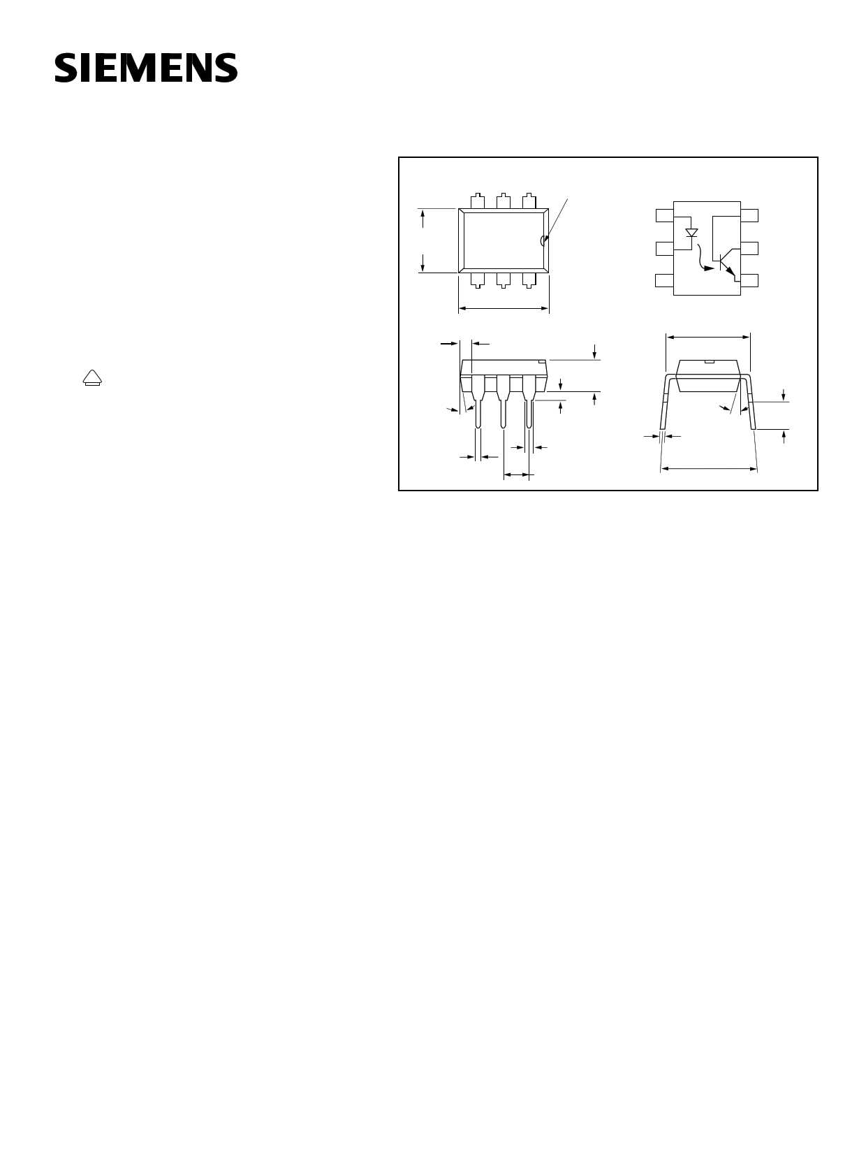
Dimensions in inches (mm)
Pin One ID
321
Anode 1
.248 (6.30)
.256 (6.50)
Cathode 2
6 Base
5 Collector
.039
(1.00)
Min.
4°
typ.
.018 (0.45)
.022 (0.55)
4 56
.335 (8.50)
.343 (8.70)
NC 3
4 Emitter
.300 (7.62)
typ.
.130 (3.30)
.150 (3.81)
.020 (.051) min.
.031 (0.80)
.035 (0.90)
.100 (2.54) typ.
18° typ.
.010 (.25)
.014 (.35)
.300 (7.62)
.347 (8.82)
.110 (2.79)
.150 (3.81)
Maximum Ratings
Emitter
Reverse Voltage.................................................................................. 6 V
Forward Current ............................................................................. 60 mA
Surge Current .................................................................................. 2.5 A
Power Dissipation ........................................................................ 100 mW
Derate Linearly from 25°C .................................................... 1.33 mW/°C
Detector
Collector-Emitter Reverse Voltage
IL1 ................................................................................................... 50 V
IL2, IL5 ............................................................................................. 70 V
Emitter-Base Reverse Voltage ............................................................. 7 V
Collector-Base Reverse Voltage ........................................................ 70 V
Collector Current ............................................................................ 50 mA
Collector Current (t<1 ms) ............................................................ 400 mA
Power Dissipation ........................................................................ 200 mW
Derate Linearly from 25°C ...................................................... 2.6 mW/°C
Package
Package Power Dissipation ........................................................ 250 mW
Derate Linearly from 25°C ...................................................... 3.3 mW/°C
Isolation Test Voltage (between emitter and detector
referred to standard climate 23°C/50%RH, DIN 50014)5300 VACRMS
Creepage..................................................................................min. 7 mm
Clearance .................................................................................min. 7 mm
Comparative Tracking Index per
DIN IEC 112/VDE 0303, part 1.........................................................175
Isolation Resistance
VIO=500 V, TA=25°C .........................................................................≥1012 Ω
VIO=500 V, TA=100°C .......................................................................≥1011 Ω
Storage Temperature .................................................... –40°C to +150°C
Operating Temperature................................................. –40°C to +100°C
Junction Temperature ..................................................................... 100°C
Soldering Temperature (2 mm from case bottom).......................... 260°C
5–1
This document was created with FrameMaker 4.0.4
1 page 
Figure 13. Collector base photocurrent versus LED current
1000
Ta = 25°C
100 Icb = 1.0357 *IF ^1.3631
10
1
.1
.01
.1
1 10
IF - LED Current - mA
100
Figure 14. Normalized photocurrent versus If and tempera-
ture
10
Normalized to:
If = 10ma, Ta = 25¡C
1
Figure 16. Normalized saturated HFE versus base current
and temperature
1.5
70°C 50°C
1.0
25°C
Normalized to:
Vce = 10V
Ib = 20µA
Ta = 25°C
-20°C
0.5
Vce = 0.4V
0.0
1
10 100
Ib - Base Current - (µA)
1000
Figure 17. Propagation delay versus collector load resistor
1000
100
Ta = 25°C, IF = 10mA
Vcc = 5 V, Vth = 1.5 V
tpHL
2.5
2.0
.1
.01
.1
NIB-Ta=-20¡C
NIb,Ta=25¡C
NIb,Ta=50¡C
NIb,Ta=70¡C
1 10
If -LED Current- mA
100
Table 15. Normalized non-saturated HFE versus base current
and temperature
1.2
70°C
Normalized to:
50°C
Ib = 20µA
1.0 25°C
Vce = 10 V
Ta = 25°C
0.8 -20°C
0.6
0.4
1
10 100
Ib - Base Current - µA
1000
10
tpLH
1.5
1
.1
1 10
RL - Collector Load Resistor - KΩ
1.0
100
IL1/2/5
5–5
5 Page | ||
| Páginas | Total 5 Páginas | |
| PDF Descargar | [ Datasheet IL2.PDF ] | |
Hoja de datos destacado
| Número de pieza | Descripción | Fabricantes |
| IL-2022 | Reed Switch | Reed Relays and Electronics |
| IL-G-15S-S3C2 | IL-G Series Connectors | Japan Aviation Electronics |
| IL-G-C2-SC-10000 | Connector | ETC |
| IL-G-xxP-S3x2 | IL-G Series Connectors | Japan Aviation Electronics |
| Número de pieza | Descripción | Fabricantes |
| SLA6805M | High Voltage 3 phase Motor Driver IC. |
Sanken |
| SDC1742 | 12- and 14-Bit Hybrid Synchro / Resolver-to-Digital Converters. |
Analog Devices |
|
DataSheet.es es una pagina web que funciona como un repositorio de manuales o hoja de datos de muchos de los productos más populares, |
| DataSheet.es | 2020 | Privacy Policy | Contacto | Buscar |