|
|
|
PDF PC904 Data sheet ( Hoja de datos )
| Número de pieza | PC904 | |
| Descripción | Built-in Voltage Detection Circuit Type Photocoupler | |
| Fabricantes | Sharp Electrionic Components | |
| Logotipo | ||
Hay una vista previa y un enlace de descarga de PC904 (archivo pdf) en la parte inferior de esta página. Total 6 Páginas | ||
|
No Preview Available !
PC904
PC904
Built-in Voltage Detection
Circuit Type Photocoupler
g Lead forming type ( I type ) and taping reel type ( P type ) are also available. ( PC904I/PC904P )
s Features
1. Built-in voltage detection circuit
2. High isolation voltage between input and
output ( Viso : 5 000V rms )
3. Standard 8-pin dual-in-line package
4. Recognizerd by UL, file No. E64380
s Applications
1. Switching power supplies
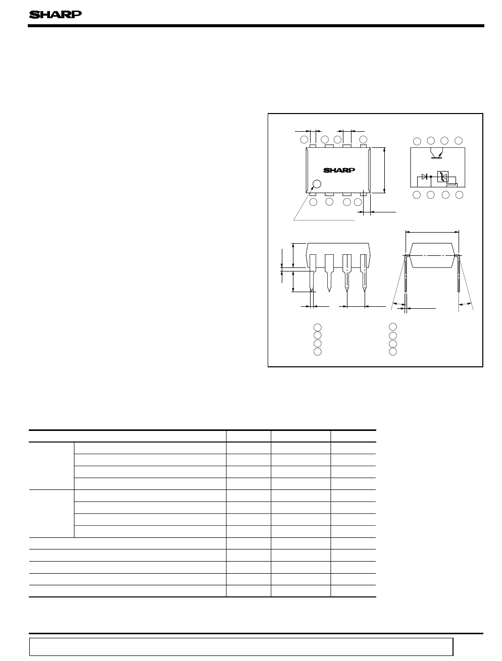
s Outline Dimensions
0.85 ± 0.3
8
76
1.2 ± 0.3
5
PC904
( Unit : mm)
Internal
connection diagram
8 76 5
1 2 34
Primary side mark
0.8 ± 0.2
1 2 34
7.62 ± 0.3
0.5 ± 0.1
θ = 0˚ to 13 ˚
2.54 ±0.25 θ 0.26 ± 0.1
θ
1 Anode
2 Cathode
3 GND
4 Reference
5 NC
6 Emitter
7 Collector
8 NC
s Absolute Maximum Ratings
Input
Output
Parameter
Anode current
Anode voltage
Reference input current
Power dissipation
Collector-emitter voltage
Emitter-collector voltage
Collector current
Collector power dissipation
Total power dissipation
*1Isolation voltage
Operating temperature
Storage temperature
*2Soldering temperature
*1 40 to 60%RH AC for 1 minute
*2 For 10 seconds
Symbol
IA
VA
I REF
P
V CEO
V ECO
IC
PC
P tot
V iso
T opr
T stg
T sol
( Ta = 25˚C)
Rating
50
30
10
250
35
6
50
150
350
5 000
- 25 to + 85
- 40 to + 125
260
Unit
mA
V
mA
mW
V
V
mA
mW
mW
V rms
˚C
˚C
˚C
“ In the absence of confirmation by device specification sheets, SHARP takes no responsibility for any defects that occur in equipment using any of SHARP's devices, shown in catalogs,
data books, etc. Contact SHARP in order to obtain the latest version of the device specification sheets before using any SHARP's device. ”
1 page 
Fig.14 OFF-state Anode Current vs.
Ambient Temperature
VA = 30V
VREF = GND
10
5
0
- 30 0 20 40 60 80 100
Ambient temperature T a (˚C)
Fig.16 Reference Input Current vs.
Ambient Temperature
3
IA = 10mA
2
1
0
- 25 0
25 50 75 100
Ambient temperature T a (˚C)
Fig.18-a Voltage Gain (1) vs. Frequency
100
IF = 2mA
T a = 25˚C
80
60
40
20
0
- 20
0.1
1 10 100
Frequency f ( kHz)
1 000
PC904
Fig.15 Reference Voltage vs.
Ambient Temperature
VK = V REF
2.60 IA = 10mA
VREF = 2.60V
2.50 2.495V
2.40 2.40V
- 30 0 20 40 60 80 100
Ambient temperature T a (˚C)
Fig.17 Reference Voltage Change vs.
Anode Voltage
0
IA= 10mA
T a= 25˚C
- 10
- 20
- 30
0 5 10 15 20 25 30 35
Anode voltage V A (V)
Test Circuit for Voltage Gain (1) vs.
Frequency
620 Ω
10k Ω
10 µ F Vin
f 10k Ω
Vo
Vo
AV1 = 20 log Vin
5 Page | ||
| Páginas | Total 6 Páginas | |
| PDF Descargar | [ Datasheet PC904.PDF ] | |
Hoja de datos destacado
| Número de pieza | Descripción | Fabricantes |
| PC900 | DEVICE SPECIFICATION FOR PHOTOCOUPLER | Sharp Electrionic Components |
| PC900 | DEVICE SPECIFICATION FOR PHOTOCOUPLER | Sharp Electrionic Components |
| PC900V | DEVICE SPECIFICATION FOR PHOTOCOUPLER | Sharp Electrionic Components |
| PC900V | Digital Output Type OPIC Photocoupler | Sharp Electrionic Components |
| Número de pieza | Descripción | Fabricantes |
| SLA6805M | High Voltage 3 phase Motor Driver IC. |
Sanken |
| SDC1742 | 12- and 14-Bit Hybrid Synchro / Resolver-to-Digital Converters. |
Analog Devices |
|
DataSheet.es es una pagina web que funciona como un repositorio de manuales o hoja de datos de muchos de los productos más populares, |
| DataSheet.es | 2020 | Privacy Policy | Contacto | Buscar |