|
|
|
PDF RF3110PCBA Data sheet ( Hoja de datos )
| Número de pieza | RF3110PCBA | |
| Descripción | TRIPLE-BAND GSM/DCS/PCS POWER AMP MODULE | |
| Fabricantes | RF Micro Devices | |
| Logotipo | ||
Hay una vista previa y un enlace de descarga de RF3110PCBA (archivo pdf) en la parte inferior de esta página. Total 12 Páginas | ||
|
No Preview Available !
Preliminary
2
Typical Applications
• 3V Dual-Band GSM Handsets
• Commercial and Consumer Systems
• Portable Battery-Powered Equipment
RF3110
TRIPLE-BAND GSM/DCS/PCS
POWER AMP MODULE
• GSM, E-GSM and DCS/PCS Products
• GPRS Class 10 Compatible
2
Product Description
The RF3110 is a high-power, high-efficiency power ampli-
fier module with integrated power control. The device is
self-contained with 50Ω input and output terminals. The
power control function is also incorporated, eliminating
the need for directional couplers, detector diodes, power
control ASICs and other power control circuitry; this
allows the module to be driven directly from the DAC out-
put. The device is designed for use as the final RF ampli-
fier in GSM/DCS and PCS handheld digital cellular
equipment and other applications in the 880MHz to
915MHz, 1710MHz to 1785MHz and 1850MHz to
1910MHz bands. On-board power control provides over
35dB of control range with an analog voltage input; and,
power down with a logic “low” for standby operation.
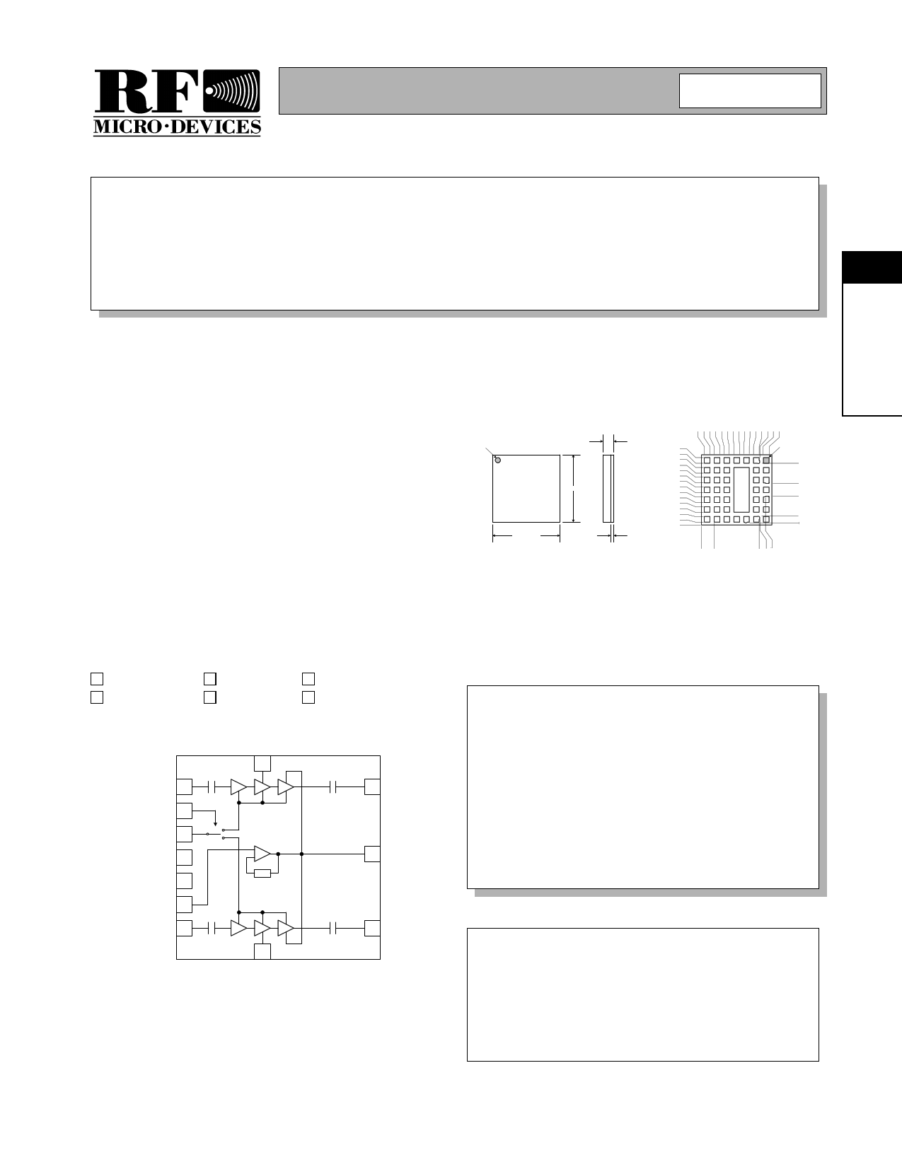
Pin 1
10.00 ± 0.10
10.00 ± 0.10
1.70
1.45
0.450
± 0.075
9.600 TYP
8.800 TYP
8.200 TYP
7.400 TYP
6.800 TYP
6.000 TYP
5.400 TYP
4.600 TYP
4.000 TYP
3.200 TYP
2.600 TYP
1.800 TYP
1.200 TYP
0.400 TYP
0.000
Pin 1
8.747
5.925
4.075
1.245
0.306
Optimum Technology Matching® Applied
Si BJT
üGaAs HBT
GaAs MESFET
Si Bi-CMOS
SiGe HBT
Si CMOS
DCS IN 1
BAND SELECT 2
TX ENABLE 3
VBATT 4
VREG 5
VRAMP 6
GSM IN 7
12
8
11 DCS OUT
10 VCC OUT
9 GSM OUT
Package Style: Module
Features
• Complete Power Control Solution
• Single 2.9V to 5.5V Supply Voltage
• +35dBm GSM Output Power at 3.5V
• +33dBm DCS/PCS Output Power at 3.5V
• 55% GSM and 55% DCS/PCS ηEFF
• 10mmx10mm Package Size
Ordering Information
RF3110
Triple-Band GSM/DCS/PCS Power Amp Module
RF3110 PCBA Fully Assembled Evaluation Board
Functional Block Diagram
RF Micro Devices, Inc.
7628 Thorndike Road
Greensboro, NC 27409, USA
Tel (336) 664 1233
Fax (336) 664 0454
http://www.rfmd.com
Rev A0 010921
2-261
1 page 
Preliminary
RF3110
Pin
1
2
3
4
5
6
7
8
9
10
11
12
Pkg
Base
Function Description
DCS IN RF input to the DCS band. This is a 50Ω input.
BAND
SELECT
Allows external control to select the GSM or DCS band with a logic high
or low. A logic low enables the GSM band whereas a logic high enables
the DCS band.
TX ENABLE This signal enables the PA module for operation with a logic high. Once
TX Enable is asserted the RF output level will increase to 0dBm.
VBATT
Power supply for the module. This should be connected to the battery.
VREG
Regulated voltage input for power control function. (2.8V nom)
VRAMP
Ramping signal from DAC. A simple RC filter may need to be con-
nected between the DAC output and the VRAMP input depending on
the baseband selected. The ramping profiles shown later in the data
sheet are recommended profiles for meeting the GSM specification for
burst timing and transient spectrum.
GSM IN RF input to the GSM band. This is a 50Ω input.
VCC2
GSM OUT
Controlled voltage input to driver stage for GSM bands. This voltage is
part of the power control function for the module. This node must be
connected to VCC out.
RF output for the GSM band. This is a 50Ω output. The output load line
matching is contained internal to the package.
VCC OUT
Controlled voltage output to feed VCC2. This voltage is part of the
power control function for the module. It can not be connected to any-
thing other than VCC2, nor can any component be placed on this node
(i.e. decoupling capacitor).
DCS OUT RF output for the DCS band. This is a 50Ω output. The output load line
matching is contained internal to the package.
VCC2
GND
Controlled voltage input to DCS driver stage. This voltage is part of the
power control function for the module. This node must be connected to
VCC out
Interface Schematic
2
Rev A0 010921
2-265
5 Page 
RF3110
2
From DAC
1 14
2 13
3 12
4 11
5 10
69
78
*Shaded area eliminated with Indirect Closed Loop using RF3110
Preliminary
2-271
Rev A0 010921
11 Page | ||
| Páginas | Total 12 Páginas | |
| PDF Descargar | [ Datasheet RF3110PCBA.PDF ] | |
Hoja de datos destacado
| Número de pieza | Descripción | Fabricantes |
| RF3110PCBA | TRIPLE-BAND GSM/DCS/PCS POWER AMP MODULE | RF Micro Devices |
| Número de pieza | Descripción | Fabricantes |
| SLA6805M | High Voltage 3 phase Motor Driver IC. |
Sanken |
| SDC1742 | 12- and 14-Bit Hybrid Synchro / Resolver-to-Digital Converters. |
Analog Devices |
|
DataSheet.es es una pagina web que funciona como un repositorio de manuales o hoja de datos de muchos de los productos más populares, |
| DataSheet.es | 2020 | Privacy Policy | Contacto | Buscar |