|
|
|
PDF TDA7427AAD1 Data sheet ( Hoja de datos )
| Número de pieza | TDA7427AAD1 | |
| Descripción | AM-FM RADIO FREQUENCY SYNTHESIZER AND IF COUNTER | |
| Fabricantes | ST Microelectronics | |
| Logotipo | ||
Hay una vista previa y un enlace de descarga de TDA7427AAD1 (archivo pdf) en la parte inferior de esta página. Total 21 Páginas | ||
|
No Preview Available !
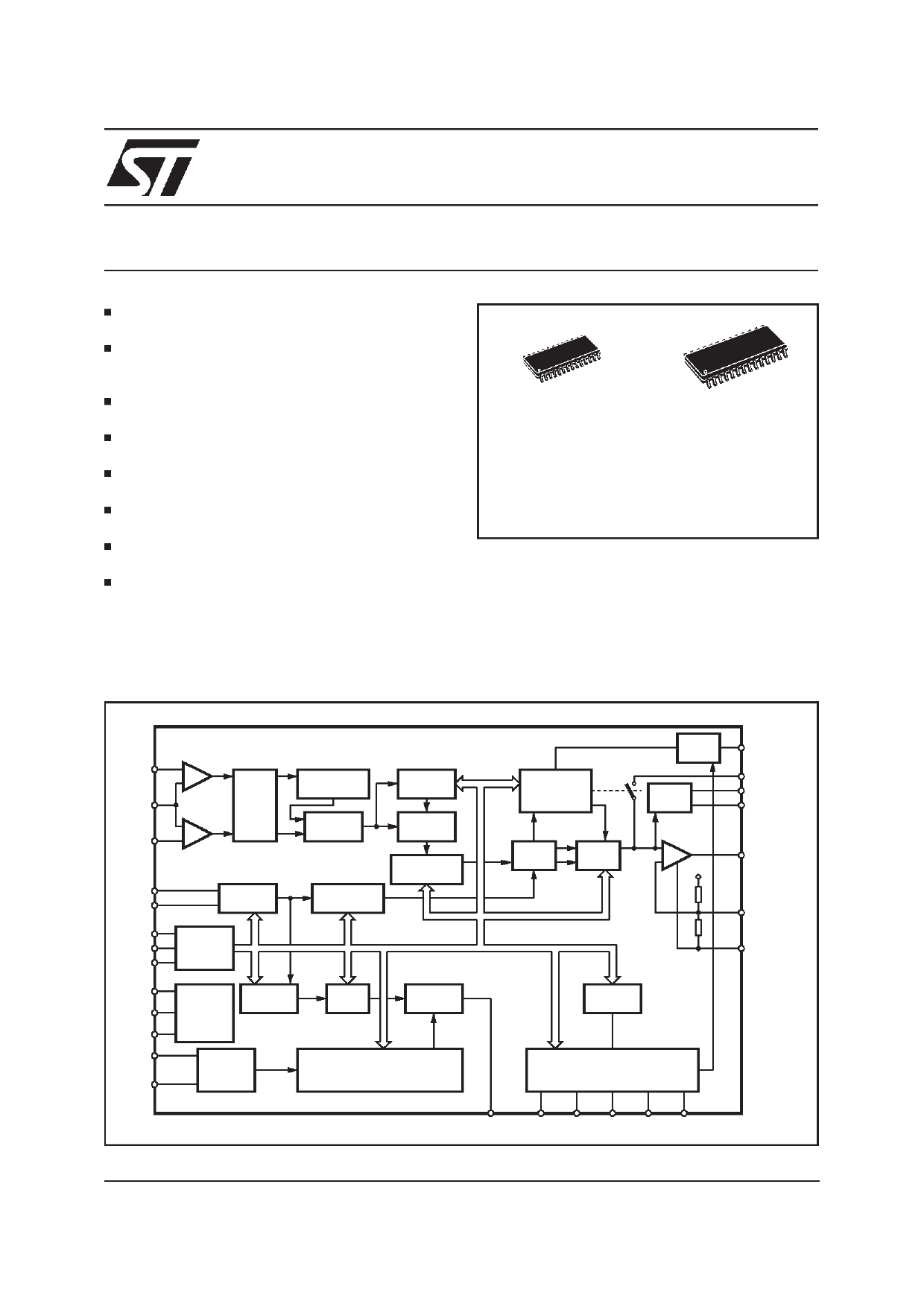
® TDA7427A
AM-FM RADIO FREQUENCY SYNTHESIZER
AND IF COUNTER
ON-CHIP REFERENCE OSCILLATOR AND
PROGRAMMABLE IF COUNTER
VHF INPUT AND PRECOUNTER FOR FRE-
QUENCIES UP TO 290MHz (SUITABLE FOR
DAB APPLICATION)
HF INPUT FOR FREQUENCIES UP TO
64MHz (SHORT WAVE BAND)
IN-LOCK DETECTOR FOR SEARCH/STOP
STATION FUNCTION
STAND-BY MODE FOR LOW POWER CON-
SUMPTION
HIGH CURRENT SOURCE FOR 0.5ms
LOCK-IN TIME
DIGITAL PORT EXTENSION WITH SIX OUT-
PUTS FOR FLEXIBILITY IN APPLICATION
FULLY PROGRAMMABLE BY I2C BUS
DESCRIPTION
The TDA7427A is a PLL frequency synthesizer
TSSOP28
SO28
ORDERING NUMBERS: TDA7427AAD (TSSOP28)
TDA7427AAD1 (SO28)
with an additional IF counting system that per-
forms all the functions needed in a complete PLL
radio tuning system for conventional and high
speed RDS tuners. The device has dedicated out-
puts for IN-LOCK detection and Search/Stop sta-
tion.
BLOCK DIAGRAM
24
FM_IN
19
HFREF
25
AM_IN
SWITCH
AM/FM
PRECOUNTER
:32/33
SWITCH
SWM/DIR
5 BIT PROG.
COUNTER
SWITCH
SWM/DIR
OSCIN
OSCOUT
9
10
REF
OSCILLATOR
ADDR
SCL
SDA
20
12 I2C BUS
13 INTERFACE
VDD2
VDD1
GNDDIG
IF_AM
IF_FM
27
SUPPLY
21 &
POWER-ON
22 RESET
14 BIT PROG
COUNTER
14
SWITCH
15 AM/FM
16 BIT PROG
COUNTER
11 BIT PROG
COUNTER
TIMER
CONTROL
11-21 BIT PROG COUNTER
D95AU372D
INLOCK
DETECTOR
PHASE
COMP
CHARGE
PUMP
SWITCH
OUT
SWITCH
LP1/LP2
17
2
3
1
DOUT1/INLOCK
LP_HC
LP_AM
LP_FM
- 28
LP_OUT
+
VDD1
4
VREF
26
GNDAN
TEST
LOGIC
PORT EXTENSION
16
SSTOP
18 5 6 7 8
DOUT2 DOUT3 DOUT4 DOUT5 DOUT6
July 1998
1/21
1 page 
TDA7427A
ELECTRICAL CHARACTERISTICS (continued)
Symbol
VIL
Parameter
Input Low Voltage
Test Condition
Min.
VIH Input High Voltage
3
IIN
VOUT
Input Current
Output Voltage SDA
acknowledge
IO = 1.6mA
-5
OSCILLATOR
tbu Build Up Time
fout = 4MHz
Cin Internal Capacitance
COUT
Internal Capacitance
fosc = 4MHz
Zin Input Impedance
fosc = 4MHz
Vin Input Voltage (for Slave Mode) fIN = 4 to 13MHz (Sinus)
capacitance coupling
300
fin Max Input frequency (for Slave VIN = 600mVPP (Sinus)
Mode)
30
LOOP FILTER (LP_FM, LP_AM, LP_HC, LP_OUT)
IIN Input Leakage Current (*)
VIN = GND; PDout = Tristate (1) -1
IIN Input Leakage Current (*)
VIN = VDD1; PDout = Tristate (1)
-1
VOL Output Voltage Low
IIN = -0.2mA
VOH Output Voltage High
IOUT = 0.2mA
9.5
IOUT Output Current Sink
10
IOUT Output Current Source
Vout = 0.5 to 9.5V
10
DOUT1/SSTOP (push-pull outputs)
VOL Output Voltage Low
IOUT = -0.1mA
VOH Output Voltage High
DOUT2 to 6 (open collector outputs)
IOUT = 0.1mA
VDD1*0.2
IOUT Output leakage Current
VOL Output Voltage Low
VOUT = 10V
IOUT = -1mA
-1
IOUT Output Current Sink
Vout = 0.5 to 9.5V
1) PD = Phase Detector
(*) LP_FM and LP_HC pins only
Typ.
0.15
20
20
0.1
0.1
0
10
30
30
0.1
4.9
0.1
0.2
3
Max.
1
+5
0.4
100
100
VDD
1
1
0.5
0.2
1
0.5
5
Unit
V
V
µA
V
ms
pF
pF
KΩ
mVpp
MHz
µA
µA
V
V
mA
mA
V
V
mA
V
mA
5/21
5 Page 
I2C BUS INTERFACE DESCRIPTION
The TDA7427A supports the I2C bus protocol.
This protocol defines any device that sends data
into the bus as a transmitter and the receiving de-
vice as the receiver. The device that controls the
transfer is the master and the device being con-
trolled is the slave. The master always initiates
data transfer and provides the clock to transmit or
receive operations.
Data Transition
Data transition on the SDA line must only occur
when the clock SCL is low. SDA transitions while
SCL is high will be interpreted as START or
STOP condition.
Start Condition
A start condition is defined by a HIGH to LOW
transition of the SDA line while SCL is at a stable
HIGH level. This START condition must precede
any command and initiate a data transfer onto the
bus. The TDA7427A continuously monitors the
SDA and SCL lines for a valid START and will not
response to any command if this condition has
not been met.
Stop Condition
A STOP condition is defined by a LOW to HIGH
transition of the SDA while the SCL line is at a stable
HIGH level. This condition terminate the communica-
tion between the devices and forces the bus interface
of the TDA7427Ainto the initial condition.
Acknowledge
Indicates a successful data transfer. The transmit-
Figure 6. Application with two loop filters
TDA7427A
ter will release the bus after sending 8 bit of data.
During the 9th clock cycle the receiver will pull the
SDA line to LOW level to indicate it has receive
the eight bits of data correctly.
Data transfer
During data transfer the TDA7427A samples the
SDA line on the leading edge of the SCL clock.
Therefore, for proper device operation the SDA
line must be stable during the SCL LOW to HIGH
transition.
Device Addressing
To start the communication between two devices,
the bus master must initiate a start instruction se-
quence, followed by an eight bit word correspond-
ing to the address of the device it is addressing.
The most significant 6 bits of the slave address
are the device type identifier.
The TDA7427A frequency synthesizer device
type is fixed as ”110001”
The next significant bit is used to address a par-
ticular device of the previous defined type con-
nected to the bus. The state of the hardwired A0
pin defines the state of this address bit. So up to
two devices could be connected on the same bus.
The last bit of the instruction defines the type of
operation to be performed:
- When set to ”1”, a read operation is selected
- When set to ”0”, a write operation is selected
The chip selection is accomplished by setting the
bit of the chip address to the corresponding status
of the A0 input.
All TDA7427A connected to the bus will compare
their own hardwired address with the slave ad-
FM VCO
+10V
VDD1
10µF
100nF
AM-FM
IF
10nF
10nF
1nF
AM VCO
10nF
3.9K
100nF
VDD2
IF_AM IF_FM FM_IN
AM_IN
820Ω
CONTROLLER
+5V
100nF
SCL
SDA
19
8
9
VDD1
10µF
15
10 11 16
TDA7427
17
20
LPOUT
Utun
1nF
1
LP_FM 27K 6.8nF
2
LP_HC 15K
LP_AM 100K
3
68nF
100nF
VREF
4
5
6
6.8nF
INLOCK/DOUT1
13
SSTOP
12
14 7
D95AU379B
OSCIN
4MHz
OSCOUT
10nF
HFREF
DOUT3
3.3nF
FM:50KHz
AM:1KHz
11/21
11 Page | ||
| Páginas | Total 21 Páginas | |
| PDF Descargar | [ Datasheet TDA7427AAD1.PDF ] | |
Hoja de datos destacado
| Número de pieza | Descripción | Fabricantes |
| TDA7427AAD | AM-FM RADIO FREQUENCY SYNTHESIZER AND IF COUNTER | ST Microelectronics |
| TDA7427AAD1 | AM-FM RADIO FREQUENCY SYNTHESIZER AND IF COUNTER | ST Microelectronics |
| Número de pieza | Descripción | Fabricantes |
| SLA6805M | High Voltage 3 phase Motor Driver IC. |
Sanken |
| SDC1742 | 12- and 14-Bit Hybrid Synchro / Resolver-to-Digital Converters. |
Analog Devices |
|
DataSheet.es es una pagina web que funciona como un repositorio de manuales o hoja de datos de muchos de los productos más populares, |
| DataSheet.es | 2020 | Privacy Policy | Contacto | Buscar |