|
|
|
PDF VFC121BP Data sheet ( Hoja de datos )
| Número de pieza | VFC121BP | |
| Descripción | Precision Single Power Supply VOLTAGE-TO-FREQUENCY CONVERTER | |
| Fabricantes | Burr-Brown Corporation | |
| Logotipo | ||
Hay una vista previa y un enlace de descarga de VFC121BP (archivo pdf) en la parte inferior de esta página. Total 8 Páginas | ||
|
No Preview Available !
® VFC121
Precision Single Power Supply
VOLTAGE-TO-FREQUENCY CONVERTER
FEATURES
q SINGLE SUPPLY OPERATION:
+4.5V to +36V
q f = 1.5MHz max
O
q LOW NONLINEARITY: 0.03% max at
100kHz, 0.1% max at 1MHz
q HIGH INPUT IMPEDANCE
q VOLTAGE REFERENCE OUTPUT
q THERMOMETER OUTPUT: 1mV/°K
APPLICATIONS
q INTEGRATING A/D CONVERSION
q ANALOG SIGNAL TRANSMISSION
q PHASE-LOCKED LOOP VCO
q GALVANICALLY ISOLATED SYSTEMS
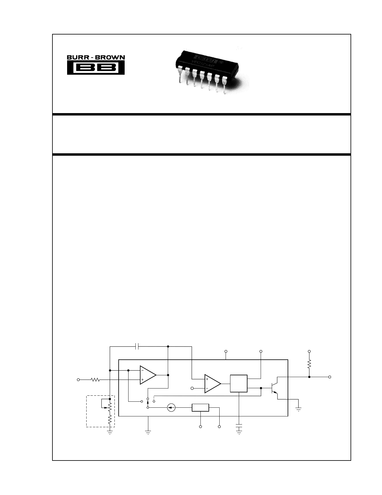
DESCRIPTION
The VFC121 is a monolithic voltage-to-frequency
converter consisting of an integrating amplifier, volt-
age reference, and one-shot charge pump circuitry.
High-frequency complementary NPN/PNP circuitry is
used to implement the charge-balance technique,
achieving speed and accuracy far superior to previous
single power supply VFCs.
The high-impedance input accepts signals from ground
potential to VS – 2.5V. Power supplies from 4.5V to
36V may be used. A 2.6V reference voltage output
may be used to excite sensors or bias external cir-
cuitry. A thermometer output voltage proportional to
absolute temperature (°K) may be used as a tempera-
ture sensor or for temperature compensation of appli-
cations circuits.
Frequency output is an open-collector transistor. A
disable pin forces the output to the high impedance
state, allowing multiple VFCs to share a common
transmission path.
12
VIN = 0 to +2V
11
RBIAS = 8kΩ
(Optional)
RIN = 8kΩ
RTRIM
RIN
CINT = 2700pF
10
Integrator
+5V
+VS
9 13
Comparator
VREF
One
Shot
IREF
VREF
Ground
(Optional)
2
4
63
5
COS = 1200pF
2.6V
VT
VPULL UP
RPULL UP
14
fOUT =
0 to 100kHz
8
International Airport Industrial Park • Mailing Address: PO Box 11400 • Tucson, AZ 85734 • Street Address: 6730 S. Tucson Blvd. • Tucson, AZ 85706
Tel: (520) 746-1111 • Twx: 910-952-1111 • Cable: BBRCORP • Telex: 066-6491 • FAX: (520) 889-1510 • Immediate Product Info: (800) 548-6132
© 1989 Burr-Brown Corporation
PDS-971A
Printed in U.S.A. March, 1992
1 page 
TYPICAL PERFORMANCE CURVES (CONT)
At TA = +25°C, VS = +5V, and RIN = 8kΩ, unless otherwise noted.
QUIESCENT CURRENT vs TEMPERATURE
10
9.5
9
8.5
VS = +36V
8
VS = +12V
7.5
VS = +5V
7
–50 –25
0
25 50 75
Ambient Temperature (°C)
100 125
6
5
4
3
2
1
0
–25
FULL SCALE GAIN DRIFT vs TEMPERATURE
fFS = 1.5MHz
fFS = 1MHz
fFS = 500kHz
fFS = 200kHz
fFS = 100kHz
fFS = 10kHz
0 25 50 75
Ambient Temperature (°C)
100
THEORY OF OPERATION
The VFC121 uses a charge-balance technique to achieve
high accuracy. The basic architecture is shown in Figure 1.
An analog integrator at the front end, consisting of a preci-
sion op amp and a feedback capacitor, CINT, provides a true
integrating approach for improved noise immunity. Use of
the non-inverting input of the op amp for the analog input
provides a high input impedance to the user.
The integrator’s output is proportional to the charge stored
on CINT plus the analog input voltage. An input voltage, VIN,
forces a current through RIN of VIN/RIN, which also flows
through CINT. This current through CINT causes the integra-
tor output to ramp positive. (Refer to the timing diagram in
Figure 2.)
When the output of the integrator ramps to VREF, the com-
parator trips, driving the output of the VFC121 Low, and
triggering the one-shot. The tripping of the comparator also
connects the reference current, IREF, to the integrator input
for the duration of the one-shot period, TOS. This switched
current causes the output of the integrator to ramp negative.
When the one-shot times out, the output of the VFC121 is
reset High, the one-shot is reset, and IREF is switched to the
output of the integrating op amp. (This causes the output of
VREF (2.6V)
1/ fOUT
FIGURE 2. Timing Diagram.
Integrator
Output
(pin 10)
Effect of
a smaller
CINT
fOUT
(pin 14)
C INT
10 9
+VS
13
12
11
VIN
Integrator
VREF
Comparator
One
Shot
RIN IREF
VREF
4
63
5
COS
VREF
VT
FIGURE 1. VFC121 Architecture.
2
14
fOUT
8
5 VFC121
®
5 Page | ||
| Páginas | Total 8 Páginas | |
| PDF Descargar | [ Datasheet VFC121BP.PDF ] | |
Hoja de datos destacado
| Número de pieza | Descripción | Fabricantes |
| VFC121BP | Precision Single Power Supply VOLTAGE-TO-FREQUENCY CONVERTER | Burr-Brown Corporation |
| Número de pieza | Descripción | Fabricantes |
| SLA6805M | High Voltage 3 phase Motor Driver IC. |
Sanken |
| SDC1742 | 12- and 14-Bit Hybrid Synchro / Resolver-to-Digital Converters. |
Analog Devices |
|
DataSheet.es es una pagina web que funciona como un repositorio de manuales o hoja de datos de muchos de los productos más populares, |
| DataSheet.es | 2020 | Privacy Policy | Contacto | Buscar |