|
|
|
PDF IRF7807D2 Data sheet ( Hoja de datos )
| Número de pieza | IRF7807D2 | |
| Descripción | MOSFET / SCHOTTKY DIODE | |
| Fabricantes | International Rectifier | |
| Logotipo | ||
Hay una vista previa y un enlace de descarga de IRF7807D2 (archivo pdf) en la parte inferior de esta página. Total 8 Páginas | ||
|
No Preview Available !
PD- 93762
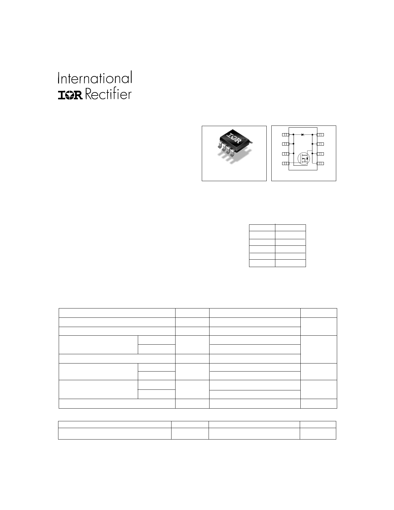
IRF7807D2
FETKY™ MOSFET / SCHOTTKY DIODE
• Co-Pack N-channel HEXFET® Power MOSFET
and Schottky Diode
• Ideal for Synchronous Rectifiers in DC-DC
Converters up to 5A Output
• Low Conduction Losses
• Low Switching Losses
• Low Vf Schottky Rectifier
Description
The FETKY™ family of Co-Pack HEXFET® MOSFETs
and Schottky diodes offers the designer an innovative,
board space saving solution for switching regulator and
power management applications. HEXFET power
MOSFETs utilize advanced processing techniques to
achieve extremely low on-resistance per silicon area.
Combining this technology with International Rectifier’s
low forward drop Schottky rectifiers results in an extremely
efficient device suitable for use in a wide variety of
portable electronics applications.
The SO-8 has been modified through a customized
leadframe for enhanced thermal characteristics.The SO-
8 package is designed for vapor phase, infrared or wave
soldering techniques.
Absolute Maximum Ratings
Parameter
Drain-Source Voltage
Gate-Source Voltage
Continuous Drain or Source
25°C
Current (VGS ≥ 4.5V)
Pulsed Drain Current
70°C
Power Dissipation
25°C
70°C
Schottky and Body Diode
25°C
Average ForwardCurrent
70°C
Junction & Storage Temperature Range
Symbol
VDS
VGS
ID
IDM
PD
IF (AV)
TJ, TSTG
Thermal Resistance
Parameter
Maximum Junction-to-Ambient
www.irf.com
RθJA
SO-8
A/S 1
8 K/D
A/S 2
7 K/D
A/S 3
6 K/D
G4
5 K/D
D
Top View
Device Features (Max Values)
VDS
RDS(on)
Qg
QSW
Qoss
IRF7807D2
30V
25mΩ
14nC
5.2nC
21.6nC
Max.
30
±12
8.3
6.6
66
2.5
1.6
3.7
2.3
–55 to 150
Max.
50
Units
V
A
W
A
°C
Units
°C/W
1
11/8/99
1 page 
IRF7807D2
0.05
0.024
0.04
0.022
VGS = 4.5V
0.03
0.020
0.02
ID = 7.0A
0.018
VGS = 10V
0.01
2.0
4.0 6.0 8.0
VGS, Gate -to -Source Voltage (V)
10.0
Fig 9. On-Resistance Vs. Gate Voltage
0.016
0
20 40 60
I D , Drain Current (A)
80
Fig 10. On-Resistance Vs. Drain Current
100
D = 0.50
10 0.20
0.10
0.05
0.02
0.01
1
0.1
0.001
SINGLE PULSE
(THERMAL RESPONSE)
PDM
t1
t2
Notes:
1. Duty factor D = t1 / t 2
2. Peak TJ = P DM x ZthJA + TA
0.01 0.1 1 10
t1 , Rectangular Pulse Duration (sec)
100
Fig 11. Maximum Effective Transient Thermal Impedance, Junction-to-Ambient (MOSFET)
www.irf.com
5
5 Page | ||
| Páginas | Total 8 Páginas | |
| PDF Descargar | [ Datasheet IRF7807D2.PDF ] | |
Hoja de datos destacado
| Número de pieza | Descripción | Fabricantes |
| IRF7807D1 | MOSFET / SCHOTTKY DIODE | International Rectifier |
| IRF7807D1PBF | HEXFET Power MOSFET | International Rectifier |
| IRF7807D2 | MOSFET / SCHOTTKY DIODE | International Rectifier |
| IRF7807D2PbF | MOSFET / SCHOTTKY DIODE | International Rectifier |
| Número de pieza | Descripción | Fabricantes |
| SLA6805M | High Voltage 3 phase Motor Driver IC. |
Sanken |
| SDC1742 | 12- and 14-Bit Hybrid Synchro / Resolver-to-Digital Converters. |
Analog Devices |
|
DataSheet.es es una pagina web que funciona como un repositorio de manuales o hoja de datos de muchos de los productos más populares, |
| DataSheet.es | 2020 | Privacy Policy | Contacto | Buscar |