|
|
|
PDF IPM6220 Data sheet ( Hoja de datos )
| Número de pieza | IPM6220 | |
| Descripción | Advanced Triple PWM and Dual Linear Power Controller for Portable | |
| Fabricantes | Intersil Corporation | |
| Logotipo | ||
Hay una vista previa y un enlace de descarga de IPM6220 (archivo pdf) en la parte inferior de esta página. Total 14 Páginas | ||
|
No Preview Available !
NOTTMRREECICSOOLM6MD2MMa3tE2EaNN(SADDhvEEaeDDielatFRbOEleRPFLNeAEbCW.E2MD00EE4NS)ITGNS
December 2000
IPM6220
FN4903.1
Advanced Triple PWM and Dual Linear
Power Controller for Portable
Applications
The IPM6220 provides a highly integrated power control and
protection solution for five output voltages required in high-
performance notebook PC applications. The IC integrates
three fixed frequency pulse-width-modulation (PWM)
controllers and two linear regulators along with monitoring and
protection circuitry into a single 24 lead SSOP package.
The two PWM controllers that regulate the system main 5V
and 3.3V voltages are implemented with synchronous-
rectified buck converters. Synchronous rectification and
hysteretic operation at light loads contribute to high efficiency
over a wide range of input voltage and load variation.
Efficiency is further enhanced by using the lower MOSFET’s
rDS(ON) as the current sense element. Input voltage feed-
forward ramp modulation, current-mode control, and internal
feed-back compensation provide fast and stable handling of
input voltage load transients encountered in advanced
portable computer chip sets.
The third PWM controller is a boost converter that regulates a
resistor selectable output voltage of nominally 12V.
Two internal linear regulators provide +5V ALWAYS and
+3.3V ALWAYS low current outputs required by the notebook
system controller.
Ordering Information
TEMP.
PART NUMBER RANGE (oC)
PACKAGE
IPM6220CA
0 to 70 24 Ld SSOP
IPM6220EVAL1 Evaluation Board
PKG.
NO.
M24.15
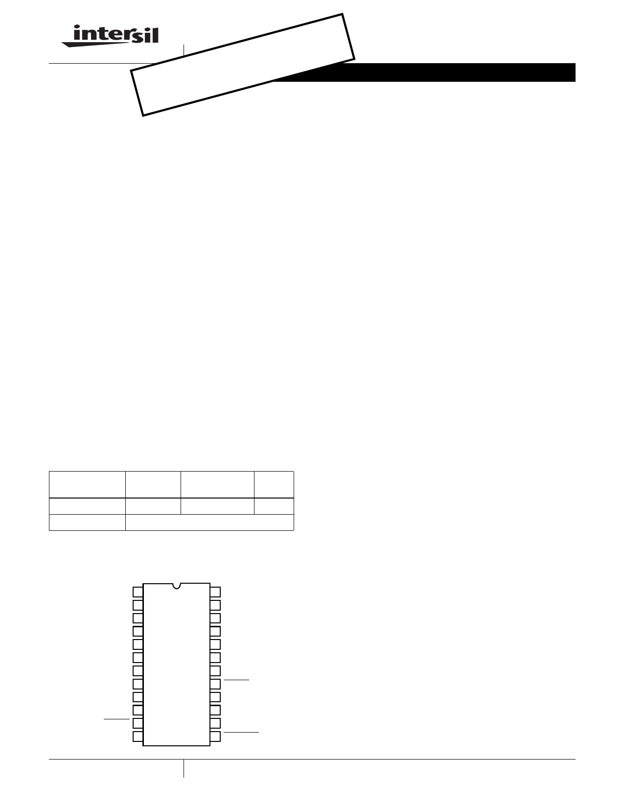
Pinout
IPM6220 (SSOP)
TOP VIEW
VBATT 1
3.3V ALWAYS 2
BOOT2 3
UGATE2 4
PHASE2 5
5V ALWAYS 6
LGATE2 7
PGND2 8
ISEN2 9
VSEN2 10
SDWN2 11
PGOOD 12
24 BOOT1
23 UGATE1
22 PHASE1
21 ISEN1
20 LGATE1
19 PGND1
18 VSEN1
17 SDWN1
16 GATE3
15 VSEN3
14 GND
13 SDWNALL
Features
• Provides Five Regulated Voltages
- +5V ALWAYS
- +3.3V ALWAYS
- +5V Main
- +3.3V Main
- +12V
• High Efficiency Over Wide Line and Load Range
- Synchronous Buck Converters on Main Outputs
- Hysteretic Operation at Light Load
• No Current-Sense Resistor Required
- Uses MOSFET’s rDS(ON)
- Optional Current-Sense Resistor for More Precision
• Operates Directly From Battery 5.6 to 22V Input
• Input Undervoltage Lock-Out (UVLO)
• Excellent Dynamic Response
- Voltage Feed-Forward and Current-Mode Control
• Monitors Output Voltages
• Synchronous Converters Operate Out of Phase
• Separate Shut-Down Pins for Advanced Configuration and
Power Interface (ACPI) Compatibility
• 300kHz Fixed Switching Frequency on Main Outputs
• Thermal Shut-Down Protection
Applications
• Mobile PCs
• Hand-Held Portable Instruments
Related Literature
• Application Note AN9915
1 CAUTION: These devices are sensitive to electrostatic discharge; follow proper IC Handling Procedures.
1-888-INTERSIL or 321-724-7143 | Intersil and Design is a trademark of Intersil Corporation. | Copyright © Intersil Corporation 2000
1 page 
IPM6220
Electrical Specifications Recommended Operating Conditions, Unless Otherwise Noted. Refer to Block and Simplified Power System
Diagrams, and Typical Application Schematic (Continued)
PARAMETER
SYMBOL
TEST CONDITIONS
MIN TYP MAX UNITS
Internal Resistance to GND on VSNS2 Pin
RVSNS2
PWM1 and PWM2 CONTROLLER GATE DRIVERS
66K Ω
Upper Drive Pull-Up Resistance
Upper Drive Pull-Down Resistance
Lower Drive Pull-Up Resistance
Lower Drive Pull-Down Resistance
PWM 3 CONVERTER
R2UGPUP
R2UGPDN
R2LGPUP
R2LGPDN
- 7 12
- 4 10
- 69
- 58
Ω
Ω
Ω
Ω
12V Feedback Regulation Voltage
VSEN3
2.472
V
12V Feedback Regulation Voltage Input
Current
IVSEN3
0.1 1.0
µA
Line and Load Regulation
Under-Voltage Shut-Down Level
Over-Voltage Threshold
PWM3 Oscillator Frequency
Maximum Duty Cycle
0.0 < IVOUT3 < 120mA, 4.9V< 5VMain <5.1V
-2
+2
VUV3 2µs delay, % Feedback Voltage at VSNS3 pin 70 75 80
VOVP3 2µs delay, % Feedback Voltage at VSNS3 pin
115 120
Fc3 85 100 115
33
%
%
%
kHz
%
PWM 3 CONTROLLER GATE DRIVERS
Pull-Up Resistance
R3GPUP
6 12
Ω
Pull-Down Resistance
R3GPDN
6 12
Ω
5V and 3.3V ALWAYS
Linear Regulator Accuracy
5V ALWAYS Output Voltage Regulation
Maximum Output Current
PWM1, 5V Output OFF (SDWN1 = 0V);
5.6V < VBATT < 22V; 0 < ILOAD < 50mA
PWM1, 5V Output ON (SDWN1 = 5V);
0 < ILOAD < 50mA
Combined 5V ALWAYS and 3.3V ALWAYS
-2.0 0.5 +2.0
%
-3.3 1.0 +2.0
%
50 mA
Current Limit
Combined 5V ALWAYS and 3.3V ALWAYS
100 180
mA
5V ALWAYS Under-Voltage Shut-Down
75 %
Bypass Switch rDS(ON)
POWER GOOD AND CONTROL FUNCTIONS
PWM1, 5V Output ON (SDWN1 = 5V)
1.3 Ω
Power Good Threshold for PWM1 and
PWM2 Output Voltages
-14 -12 -10
%
PGOOD Leakage Current
PGOOD Voltage Low
PGOOD Minimum Pulse Width
SDWN1, 2, - Low (Off)
IPGLKG
VPGOOD
TPGmin
VPULLUP = 5.0V
IPGOOD = -4mA
- - 1.0
0.2 0.5
10
0.8
µA
V
µs
V
SDWN1, 2, - High (On)
4.3 V
SDWNALL - High (On)
2.4 V
SDWNALL - Low (Off)
Over-Temperature Shutdown
Over-Temperature Hysteresis
SDWNALL, Hysteresis
40 mV
150 oC
25 oC
5
5 Page 
IPM6220
determined by the ESR (Equivalent Series Resistance) and
voltage rating requirements as well as actual capacitance
requirements. The output voltage ripple is due to the
inductor ripple current and the ESR of the output capacitors
as defined by:
VRIPPLE = ∆IL × ESR
where, ∆IL is calculated in the Inductor Selection section.
High frequency decoupling capacitors should be placed as
close to the power pins of the load as physically possible. Be
careful not to add inductance in the circuit board wiring that
could cancel the usefulness of these low inductance
components. Consult with the manufacturer of the load
circuitry for specific decoupling requirements.
Use only specialized low-ESR capacitors intended for
switching-regulator applications, at 300kHz, for the bulk
capacitors. In most cases, multiple electrolytic capacitors of
small case size perform better than a single large case
capacitor.
The stability requirement on the selection of the output
capacitor is that the ‘ESR zero’, fZ, be between 1.2kHz and
30kHz. This range is set by an internal, single compensation
zero at 6kHz. The ESR zero can be a factor of five on either
side of the internal zero and still contribute to increased
phase margin of the control loop. Therefore:
COUT
=
---------------------1----------------------
2 × π × ESR × fZ
In conclusion, the output capacitors must meet three criteria: By
varying the values of the soft-start capacitors, it is possible to
provide sequencing of the main outputs at start-up.
1. They must have sufficient bulk capacitance to sustain the
output voltage during a load transient while the output
inductor current is slewing to the value of the load
transient
2. The ESR must be sufficiently low to meet the desired
output voltage ripple due to the output inductor current,
and
3. The ESR zero should be placed, in a rather large range,
to provide additional phase margin.
3.3V ALWAYS and 5V ALWAYS Output Capacitors
The output capacitors for the linear regulators insure stability
and provide dynamic load current. The 3.3V ALWAYS and
the 5V ALWAYS linear regulators should have, as a
minimum, 10µF capacitors on their outputs.
3.3V Main and 5V Main PWM Output Inductor
Selection
The PWM converters require output inductors. The output
inductor is selected to meet the output voltage ripple
requirements. The inductor value determines the converter’s
ripple current and the ripple voltage is a function of the ripple
current and output capacitor(s) ESR. The ripple voltage
expression is given in the capacitor selection section and the
ripple current is approximated by the following equation:
∆IL
=
V-----I--N-----–----V-----O----U----T--
FS × L
×
-V----O----U----T--
VIN
Input Capacitor Selection
The important parameters for the bulk input capacitor(s) are
the voltage rating and the RMS current rating. For reliable
operation, select bulk input capacitors with voltage and
current ratings above the maximum input voltage and largest
RMS current required by the circuit. The capacitor voltage
rating should be at least 1.25 times greater than the
maximum input voltage and 1.5 times is a conservative
guideline.
The AC RMS input current varies with load as shown in
Figure 9. Depending on the specifics of the input power and
it’s impedance, most (or all) of this current is supplied by the
input capacitor(s). Figure 9 also shows the advantage of
having the PWM converters operating out of phase. If the
converters were operating in phase, the combined RMS
current would be the algebraic sum, which is a much larger
value as shown. The combined out-of-phase current is the
square root of the sum of the square of the individual
reflected currents and is significantly less than the combined
in-phase current.
5
4.5
4
3.5
3
2.5
2
1.5
1
0.5
0
0
IN PHASE
OUT OF PHASE
3.3V
1234
3.3V AND 5V LOAD CURRENT
5V
5
FIGURE 9. INPUT RMS CURRENT vs LOAD
Use a mix of input bypass capacitors to control the voltage
ripple across the MOSFETs. Use ceramic capacitors for the
high frequency decoupling and bulk capacitors to supply the
RMS current. Small ceramic capacitors can be placed very
close to the upper MOSFET to suppress the voltage induced
in the parasitic circuit impedances.
For board designs that allow through-hole components, the
Sanyo OS-CON® series offer low ESR and good
temperature performance.
For surface mount designs, solid tantalum capacitors can be
used, but caution must be exercised with regard to the
capacitor surge current rating. These capacitors must be
capable of handling the surge-current at power-up. The TPS
series available from AVX is surge current tested.
11 OS-CON® is a registered trademark of Sanyo Electric Company, Ltd. (Japan)
11 Page | ||
| Páginas | Total 14 Páginas | |
| PDF Descargar | [ Datasheet IPM6220.PDF ] | |
Hoja de datos destacado
| Número de pieza | Descripción | Fabricantes |
| IPM6220 | Advanced Triple PWM and Dual Linear Power Controller for Portable | Intersil Corporation |
| IPM6220A | Advanced Triple PWM and Dual Linear Power Controller | Intersil Corporation |
| IPM6220EVAL1 | Advanced Triple PWM Only Mode and Dual Linear Power Controller for Portable Applications | Intersil Corporation |
| Número de pieza | Descripción | Fabricantes |
| SLA6805M | High Voltage 3 phase Motor Driver IC. |
Sanken |
| SDC1742 | 12- and 14-Bit Hybrid Synchro / Resolver-to-Digital Converters. |
Analog Devices |
|
DataSheet.es es una pagina web que funciona como un repositorio de manuales o hoja de datos de muchos de los productos más populares, |
| DataSheet.es | 2020 | Privacy Policy | Contacto | Buscar |