|
|
|
PDF 74ACTQ74SC Data sheet ( Hoja de datos )
| Número de pieza | 74ACTQ74SC | |
| Descripción | Quiet Series Dual D-Type Positive Edge-Triggered Flip-Flop | |
| Fabricantes | Fairchild Semiconductor | |
| Logotipo | ||
Hay una vista previa y un enlace de descarga de 74ACTQ74SC (archivo pdf) en la parte inferior de esta página. Total 8 Páginas | ||
|
No Preview Available !
March 1993
Revised November 1999
74ACTQ74
Quiet Series Dual D-Type
Positive Edge-Triggered Flip-Flop
General Description
The 74ACTQ74 is a dual D-type flip-flop with Asynchro-
nous Clear and Set inputs and complementary (Q, Q) out-
puts. Information at the input is transferred to the outputs
on the positive edge of the clock pulse. Clock triggering
occurs at a voltage level of the clock pulse and is not
directly related to the transition time of the positive-going
pulse. After the Clock Pulse input threshold voltage has
been passed, the Data input is locked out and information
present will not be transferred to the outputs until the next
rising edge of the Clock Pulse input.
The ACTQ74 utilizes Fairchild Quiet Series technology to
guarantee quiet output switching and improved dynamic
threshold performance. FACT Quiet Series features
GTO output control and undershoot corrector in addition
to a split ground bus for superior performance.
Asynchronous Inputs:
LOW input to SD (Set) sets Q to HIGH level
LOW input to CD (Clear) sets Q to LOW level
Clear and Set are independent of clock
Simultaneous LOW on CD and SD makes
both Q and Q HIGH
Features
s ICC reduced by 50%
s Guaranteed simultaneous switching noise level and
dynamic threshold performance
s Guaranteed pin-to-pin skew AC performance
s Improved latch-up immunity
s 4 kV minimum ESD immunity
s TTL-compatible inputs
Ordering Code:
Order Number Package Number
Package Description
74ACTQ74SC
74ACTQ74SJ
74ACTQ74PC
M14A
M14D
N14A
14-Lead Small Outline Integrated Circuit (SOIC), JEDEC MS-120, 0.150 Narrow
14-Lead Small Outline Package (SOP), EIAJ TYPE II, 5.3mm Wide
14-Lead Plastic Dual-In-Line Package (PDIP), JEDEC MS-001, 0.300 Wide
Device also available in Tape and Reel. Specify by appending suffix letter “X” to the ordering form.
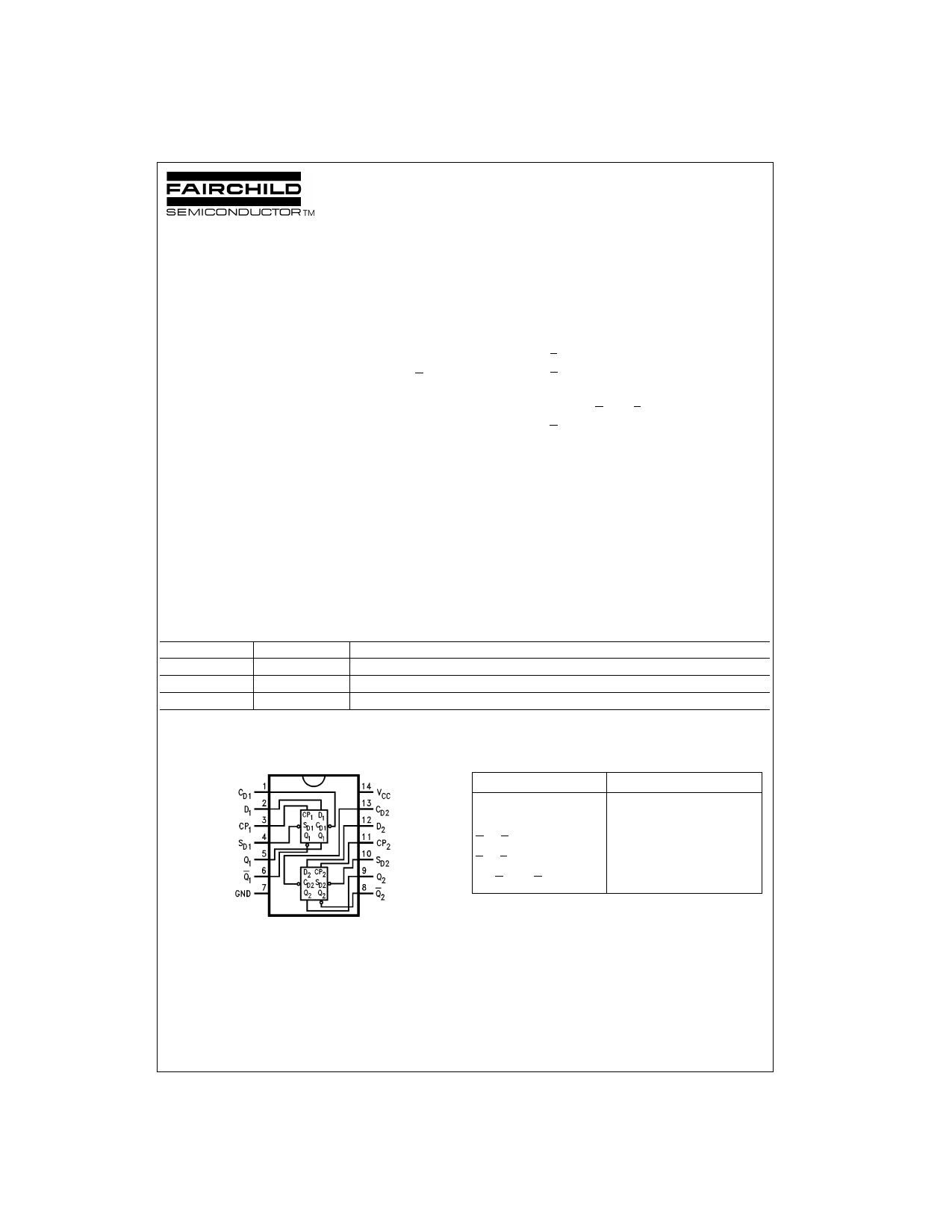
Connection Diagram
Pin Descriptions
Pin Names
D1, D2
CP1, CP2
CD1, CD2
SD1, SD2
Q1, Q1, Q2, Q2
Description
Data Inputs
Clock Pulse Inputs
Direct Clear Inputs
Direct Set Inputs
Outputs
FACT, FACT Quiet Series and GTO are trademarks of Fairchild Semiconductor Corporation.
© 1999 Fairchild Semiconductor Corporation DS010920
www.fairchildsemi.com
1 page 
FACT Noise Characteristics
The setup of a noise characteristics measurement is critical
to the accuracy and repeatability of the tests. The following
is a brief description of the setup used to measure the
noise characteristics of FACT.
Equipment:
Hewlett Packard Model 8180A Word Generator
PC-163A Test Fixture
Tektronics Model 7854 Oscilloscope
Procedure:
1. Verify Test Fixture Loading: Standard Load 50 pF,
500Ω.
2. Deskew the HFS generator so that no two channels
have greater than 150 ps skew between them. This
requires that the oscilloscope be deskewed first. It is
important to deskew the HFS generator channels
before testing. This will ensure that the outputs switch
simultaneously.
3. Terminate all inputs and outputs to ensure proper load-
ing of the outputs and that the input levels are at the
correct voltage.
4. Set the HFS generator to toggle all but one output at a
frequency of 1 MHz. Greater frequencies will increase
DUT heating and effect the results of the measure-
ment.
VOHV and VOLP are measured with respect to ground reference.
Input pulses have the following characteristics: f = 1 MHz, tr = 3 ns,
tf = 3 ns, skew < 150 ps.
FIGURE 1. Quiet Output Noise Voltage Waveforms
5. Set the HFS generator input levels at 0V LOW and 3V
HIGH for ACT devices and 0V LOW and 5V HIGH for
AC devices. Verify levels with an oscilloscope.
VOLP/VOLV and VOHP/V OHV:
• Determine the quiet output pin that demonstrates the
greatest noise levels. The worst case pin will usually be
the furthest from the ground pin. Monitor the output volt-
ages using a 50Ω coaxial cable plugged into a standard
SMB type connector on the test fixture. Do not use an
active FET probe.
• Measure VOLP and VOLV on the quiet output during the
worst case transition for active and enable. Measure
VOHP and VOHV on the quiet output during the worst
case transition for active and enable.
• Verify that the GND reference recorded on the oscillo-
scope has not drifted to ensure the accuracy and repeat-
ability of the measurements.
VILD and VIHD:
• Monitor one of the switching outputs using a 50Ω coaxial
cable plugged into a standard SMB type connector on
the test fixture. Do not use an active FET probe.
• First increase the input LOW voltage level, VIL, until the
output begins to oscillate or steps out a min of 2 ns.
Oscillation is defined as noise on the output LOW level
that exceeds VIL limits, or on output HIGH levels that
exceed VIH limits. The input LOW voltage level at which
oscillation occurs is defined as VILD.
• Next decrease the input HIGH voltage level, VIH, until
the output begins to oscillate or steps out a min of 2 ns.
Oscillation is defined as noise on the output LOW level
that exceeds V IL limits, or on output HIGH levels that
exceed VIH limits. The input HIGH voltage level at which
oscillation occurs is defined as V IHD.
• Verify that the GND reference recorded on the oscillo-
scope has not drifted to ensure the accuracy and repeat-
ability of the measurements.
FIGURE 2. Simultaneous Switching Test Circuit
5 www.fairchildsemi.com
5 Page | ||
| Páginas | Total 8 Páginas | |
| PDF Descargar | [ Datasheet 74ACTQ74SC.PDF ] | |
Hoja de datos destacado
| Número de pieza | Descripción | Fabricantes |
| 74ACTQ74SC | Quiet Series Dual D-Type Positive Edge-Triggered Flip-Flop | Fairchild Semiconductor |
| 74ACTQ74SJ | Quiet Series Dual D-Type Positive Edge-Triggered Flip-Flop | Fairchild Semiconductor |
| Número de pieza | Descripción | Fabricantes |
| SLA6805M | High Voltage 3 phase Motor Driver IC. |
Sanken |
| SDC1742 | 12- and 14-Bit Hybrid Synchro / Resolver-to-Digital Converters. |
Analog Devices |
|
DataSheet.es es una pagina web que funciona como un repositorio de manuales o hoja de datos de muchos de los productos más populares, |
| DataSheet.es | 2020 | Privacy Policy | Contacto | Buscar |