|
|
|
PDF LX1663 Data sheet ( Hoja de datos )
| Número de pieza | LX1663 | |
| Descripción | SINGLE-CHIP PROGRAMMABLE PWM CONTROLLERS WITH 5-BIT DAC | |
| Fabricantes | Microsemi Corporation | |
| Logotipo | ||
Hay una vista previa y un enlace de descarga de LX1663 (archivo pdf) en la parte inferior de esta página. Total 15 Páginas | ||
|
No Preview Available !
T H E I N F I N I T E P O W E R O F I N N O VAT I O N
L I N D O C # : 1662
LX1662/62A, LX1663/63A
SINGLE-CHIP PROGRAMMABLE PWM CONTROLLERS WITH 5-BIT DAC
PRODUCTION DATA SHEET
DESCRIPTION
The LX1662/62A and LX1663/63A are
Monolithic Switching Regulator Con-
troller IC’s designed to provide a low cost,
high performance adjustable power supply
for advanced microprocessors and other
applications requiring a very fast transient
response and a high degree of accuracy.
Short-Circuit Current Limiting with-
out Expensive Current Sense Resistors.
Current-sensing mechanism can use PCB
trace resistance or the parasitic resistance of
the main inductor. The LX1662A and
LX1663A have reduced current sense com-
parator threshold for optimum perfor-
mance using a PCB trace. For applications
requiring a high degree of accuracy, a
conventional sense resistor can be used to
sense current.
Programmable Synchronous Recti-
fier Driver for CPU Core. The main
output is adjustable from 1.3V to 3.5V using
a 5-bit code. The IC can read a VID signal
set by a DIP switch on the motherboard, or
hardwired into the processor’s package (as
in the case of Pentium® Pro and Pentium II
processors). The 5-bit code adjusts the
output voltage between 1.30 and 2.05V in
50mV increments and between 2.0 and 3.5V
in 100mV increments, conforming to the
Intel Corporation specification. The device
can drive dual MOSFET’s resulting in typical
efficiencies of 85 - 90% even with loads in
excess of 10 amperes. For cost sensitive
applications, the bottom MOSFET can be
replaced with a Schottky diode (non-syn-
chronous operation).
Smallest Package Size. The LX1662 is
available in a narrow body 14-pin surface
mount IC package for space sensitive appli-
cations. The LX1663 provides the additional
functions of Over Voltage Protection (OVP)
and Power Good (PWRGD) output drives
for applications requiring output voltage
monitoring and protection functions.
Ultra-Fast Transient Response Re-
duces System Cost. The modulated off-
time architecture results in the fastest tran-
sient response for a given inductor, reduc-
ing output capacitor requirements, and re-
ducing the total regulator system cost.
Over-Voltage Protection and Power
Good Flag. The OVP output in the LX1663
& LX1663A can be used to drive an SCR
crowbar circuit to protect the load in the
event of a short-circuit of the main MOSFET.
The LX1663 & LX1663A also have a logic-
level Power Good Flag to signal when the
output voltage is out of specified limits.
IMPORTANT: For the most current data, consult LinFinity's web site: http://www.linfinity.com.
PRODUCT HIGHLIGHT
KEY FEATURES
I 5-bit Programmable Output For CPU Core
Supply
I No Sense Resistor Required For Short-
Circuit Current Limiting
I Designed To Drive Either Synchronous Or
Non-Synchronous Output Stages
I Lowest System Cost Possible For Price-
Sensitive Pentium And Pentium II Class
Applications
I Soft-Start Capability
I Modulated, Constant Off-Time Architecture
For Fast Transient Response And Simple
System Design
I Available Over-Voltage Protection (OVP)
Crowbar Driver And Power Good Flag
(LX1663 only)
I Small, Surface-Mount Packages
A P P L I C AT I O N S
I Socket 7 Microprocessor Supplies
(including Intel Pentium Processor, AMD-
K6TM And Cyrix® 6x86TM, Gx86TM and M2TM
Processors)
I Pentium II and Deschutes Processor & L2-
Cache Supplies
I Voltage Regulator Modules
I General Purpose DC:DC Converter
Applications
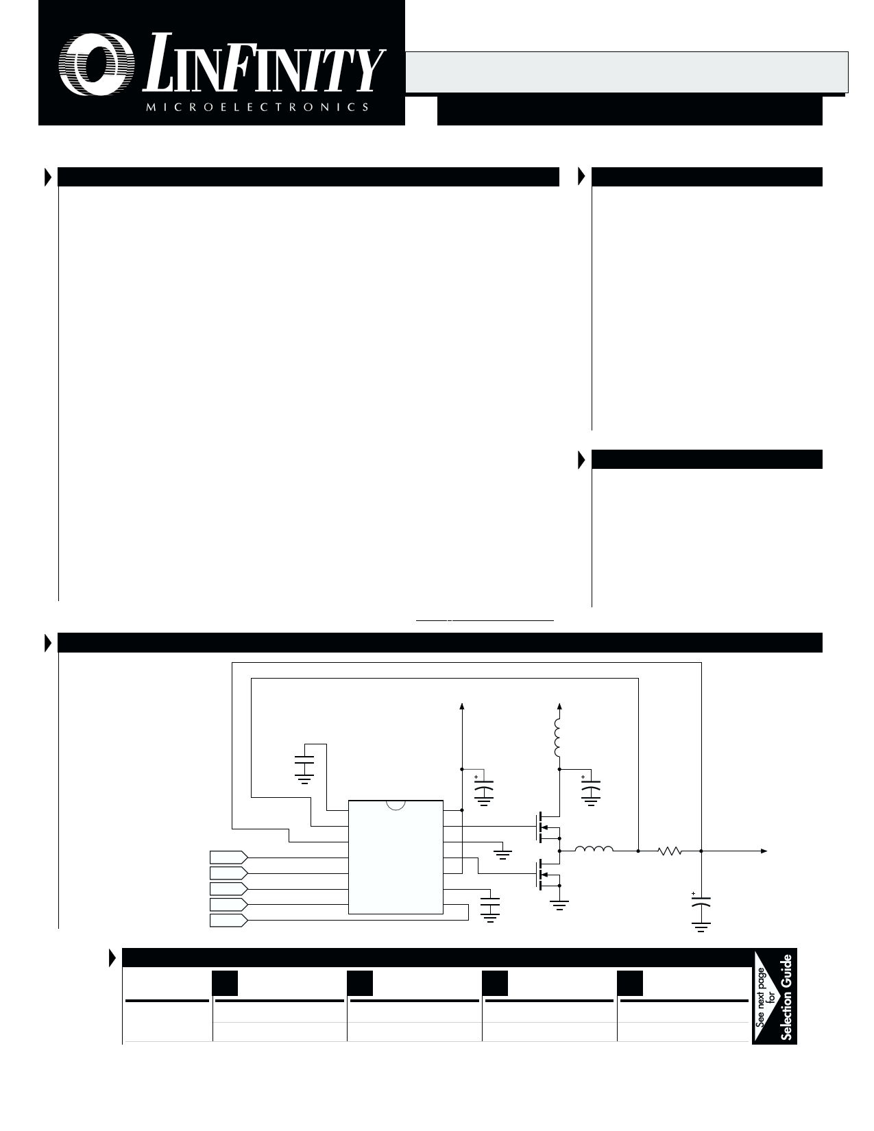
LX1662
IN A PENTIUM/PENTIUM II
SINGLE-CHIP POWER
SUPPLY SOLUTION
C3
0.1µF
VID0
VID1
VID2
VID3
VID4
12V 5V
U1
LX1662
1 SS
2 INV
V3
CC_CORE
4 VID0
5 VID1
6 VID2
7 VID3
VC1 14
TDRV 13
GND 12
BDRV 11
VCC 10
CT 9
VID4 8
14-pin, Narrow Body SOIC
L2
1µH
C5
1µF
Q1
IRL3102
6.3V
1500µF x3
C2
C8
680pF
L1, 2.5µH
R1
Q2
IRL3303
2.5m9
6.3V, 1500µF x 3**
** Three capacitors for Pentium
Four capacitors for Pentium II
Supply Voltage VOUT
for CPU Core
C1
TA (°C)
PACKAGE ORDER INFORMATION
N
Plastic DIP
14-pin
N
Plastic DIP
16-pin
D
Plastic SOIC
14-pin
D
Plastic SOIC
16-pin
0 to 70
LX1662CN
LX1662ACN
LX1663CN
LX1663ACN
LX1662CD
LX1662ACD
LX1663CD
LX1663ACD
Note: All surface-mount packages are available in Tape & Reel. Append the letter "T" to part number. (i.e. LX1662CDT)
Copyright © 1999
Rev. 1.1 11/99
LINFINITY MICROELECTRONICS INC.
11861 WESTERN AVENUE, GARDEN GROVE, CA. 92841, 714-898-8121, FAX: 714-893-2570
1
1 page 
PRODUCT DATABOOK 1996/1997
LX1662/62A, LX1663/63A
SINGLE-CHIP PROGRAMMABLE PWM CONTROLLERS WITH 5-BIT DAC
PRODUCTION DATA SHEET
CHARACTERISTICS CURVES
95
90
85
80
Output Set Point
EFFICIENCY AT 3.1V
75 EFFICIENCY AT 2.8V
EFFICIENCY AT 1.8V
70
1 2 3 4 5 6 7 8 9 10 11 12 13 14
IOUT (A)
FIGURE 2 — Efficiency Test Results:
Non-Synchronous Operation, V = 5V
IN
100
95
90
85
80
Output Set Point
EFFICIENCY AT 3.1V
75 EFFICIENCY AT 2.8V
EFFICIENCY AT 1.8V
70
1 2 3 4 5 6 7 8 9 10 11 12 13 14
IOUT (A)
FIGURE 3 — Efficiency Test Results:
Synchronous Operation, V = 5V
IN
90
85
80
75
70
Output Set Point
1.8V EFFICIENCY
65 2.8V EFFICIENCY
3.3V EFFICIENCY
60
1 2 3 4 5 6 7 8 9 10 11 12 13 14
IOUT (A)
FIGURE 4 — Efficiency Test Results: Synchronous Operation, VIN = 12V.
Note: Non-synchronous operation not recommended for 12V operation, due to power loss in Schottky diode.
Copyright © 1999
Rev. 1.1 11/99
5
5 Page 
PRODUCT DATABOOK 1996/1997
LX1662/62A, LX1663/63A
SINGLE-CHIP PROGRAMMABLE PWM CONTROLLERS WITH 5-BIT DAC
PRODUCTION DATA SHEET
Ref
C2
C1
C8
C3
C5
L1
L2
Q1
Q2
R1
U1
Total
BILL OF MATERIALS
LX1662 Bill of Materials (Refer to Product Highlight)
Description
Part Number / Manufacturer
1500µF, 6.3V capacitor
1500µF, 6.3V capacitor
680pF
0.1µF
1µF, 16V
5µF Inductor
1µF Inductor
MOSFET
MOSFET
2.5mΩ Sense Resistor (PCB trace)
Controller IC
MV-GX Sanyo
MV-GX Sanyo
SMD Cap
SMD Cap
SMD Ceramic
HM0096832 BI
IRL3102 International Rectifier or equivalent
IRL3303 International Rectifier or equivalent
LX1662CD Linfinity
Qty.
2
4
1
1
1
1
1
1
1
1
1
15
USING THE LX1662/63 DEVICES
The LX1662/63 devices are very easy to design with, requiring
only a few simple calculations to implement a given design. The
following procedures and considerations should provide effec-
tive operation for virtually all applications. Refer to the Appli-
cation Information section for component reference designa-
tors.
TIMING CAPACITOR SELECTION
The frequency of operation of the LX166x is a function of duty
cycle and OFF-time. The OFF-time is proportional to the timing
capacitor (which is shown as C8 in all application schematics in
this data sheet), and is modulated to minimize frequency
variations with duty cycle. The frequency is constant, during
steady-state operation, due to the modulation of the OFF-time.
The timing capacitor (CT) should be selected using the
following equation:
CT =
(1 - VOUT /VIN ) * IDIS
fS (1.52 - 0.29* VOUT)
Where IDIS is fixed at 200µA and fS is the switching frequency
(recommended to be around 200kHz for optimal operation and
component selection).
When using a 5V input voltage, the switching frequency (fS)
can be approximated as follows:
CT = 0.621 *
IDIS
fS
Choosing a 680pF capacitor will result in an operating
frequency of 183kHz at VOUT = 2.8V. When a 12V power input
is used, he capacitor value must be changed (the optimal timing
capacitor for 12V input will be in the range of 1000-1500pF).
L OUTPUT INDUCTOR SELECTION
1
The inductance value chosen determines the ripple current
present at the output of the power supply. Size the inductance
to allow a nominal ±10% swing above and below the nominal DC
load current, using the equation L = VL * ∆T/∆I, where ∆T is the
OFF-time, VL is the voltage across the inductor during the OFF-
time, and ∆I is peak-to-peak ripple current in the inductor. Be
sure to select a high-frequency core material which can handle
the DC current, such as 3C8, which is sized for the correct power
level. Typical inductance values can range from 2 to 10µH.
Note that ripple current will increase with a smaller inductor.
Exceeding the ripple current rating of the capacitors could cause
reliability problems.
Copyright © 1999
Rev. 1.1 11/99
11
11 Page | ||
| Páginas | Total 15 Páginas | |
| PDF Descargar | [ Datasheet LX1663.PDF ] | |
Hoja de datos destacado
| Número de pieza | Descripción | Fabricantes |
| LX1660 | ADVANCED PWM CONTROLLER | Microsemi Corporation |
| LX1661 | ADVANCED PWM CONTROLLER | Microsemi Corporation |
| LX1662 | SINGLE-CHIP PROGRAMMABLE PWM CONTROLLERS WITH 5-BIT DAC | Microsemi Corporation |
| LX1662A | SINGLE-CHIP PROGRAMMABLE PWM CONTROLLERS WITH 5-BIT DAC | Microsemi Corporation |
| Número de pieza | Descripción | Fabricantes |
| SLA6805M | High Voltage 3 phase Motor Driver IC. |
Sanken |
| SDC1742 | 12- and 14-Bit Hybrid Synchro / Resolver-to-Digital Converters. |
Analog Devices |
|
DataSheet.es es una pagina web que funciona como un repositorio de manuales o hoja de datos de muchos de los productos más populares, |
| DataSheet.es | 2020 | Privacy Policy | Contacto | Buscar |