|
|
|
PDF HUF76409D3S Data sheet ( Hoja de datos )
| Número de pieza | HUF76409D3S | |
| Descripción | 17A/ 60V/ 0.071 Ohm/ N-Channel/ Logic Level UltraFET Power MOSFET | |
| Fabricantes | Intersil Corporation | |
| Logotipo | ||
Hay una vista previa y un enlace de descarga de HUF76409D3S (archivo pdf) en la parte inferior de esta página. Total 9 Páginas | ||
|
No Preview Available !
Data Sheet
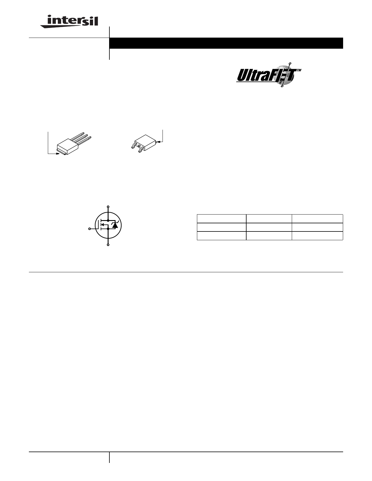
HUF76409D3, HUF76409D3S
October 1999 File Number 4665.1
17A, 60V, 0.071 Ohm, N-Channel, Logic
Level UltraFET Power MOSFET
Packaging
JEDEC TO-251AA
JEDEC TO-252AA
DRAIN
(FLANGE)
SOURCE
DRAIN
GATE
HUF76409D3
DRAIN
(FLANGE)
GATE
SOURCE
HUF76409D3S
Symbol
D
G
S
Features
• Ultra Low On-Resistance
- rDS(ON) = 0.063Ω, VGS = 10V
- rDS(ON) = 0.071Ω, VGS = 5V
• Simulation Models
- Temperature Compensated PSPICE® and SABER©
Electrical Models
- Spice and SABER© Thermal Impedance Models
- www.Intersil.com
• Peak Current vs Pulse Width Curve
• UIS Rating Curve
• Switching Time vs RGS Curves
Ordering Information
PART NUMBER
PACKAGE
BRAND
HUF76409D3
TO-251AA
76409D
HUF76409D3S
TO-252AA
76409D
NOTE: When ordering, use the entire part number. Add the suffix T to
obtain the TO-252AA variant in tape and reel, e.g., HUF76409D3ST.
Absolute Maximum Ratings TC = 25oC, Unless Otherwise Specified
HUF76409D3, HUF76409D3SS UNITS
Drain to Source Voltage (Note 1) . . . . . . . . . . . . . . . . . . . . . . . . . . . . . . . . . . . . . . . . . . VDSS
Drain to Gate Voltage (RGS = 20kΩ) (Note 1) . . . . . . . . . . . . . . . . . . . . . . . . . . . . . . . . VDGR
Gate to Source Voltage . . . . . . . . . . . . . . . . . . . . . . . . . . . . . . . . . . . . . . . . . . . . . . . . . . VGS
Drain Current
Continuous
Continuous
(TC=
(TC=
25oC,
25oC,
VGS
VGS
=
=
5V) . . . . . . .
10V) (Figure
..
2)
.
.
.
.
.
.
.
.
.
.
.
.
.
.
.
.
.
.
.
.
.
.
.
.
.
.
.
.
.
.
.
.
.
.
.
.
.
.
.
.
.
.
.
.
.
.
.
.
.
.
.
.
.
.
.
.
.
.
.
.
.
.
.
.
ID
ID
Continuous (TC= 135oC, VGS = 5V) . . . . . . . . . . . . . . . . . . . . . . . . . . . . . . . . . . . . . . . . ID
Continuous (TC= 135oC, VGS = 4.5V) (Figure 2) . . . . . . . . . . . . . . . . . . . . . . . . . . . . . . ID
Pulsed Drain Current . . . . . . . . . . . . . . . . . . . . . . . . . . . . . . . . . . . . . . . . . . . . . . . . . . .IDM
Pulsed Avalanche Rating . . . . . . . . . . . . . . . . . . . . . . . . . . . . . . . . . . . . . . . . . . . . . . . . .UIS
60
60
±16
17
18
8
8
Figure 4
Figures 6, 17, 18
V
V
V
A
A
A
A
Power Dissipation . . .
Derate Above 25oC
.
.
.
.
.
.
.
.
.
.
.
.
.
.
.
.
.
.
.
.
.
.
.
.
.
.
.
.
.
.
.
.
.
.
.
.
.
.
.
.
.
.
.
.
.
.
.
.
.
.
.
.
.
.
.
.
.
.
.
.
.
.
.
.
.
.
.
.
.
.
.
.
.
.
.
.
.
.
.
.
.
.
.
.
.
.
.
.
.
.
.
.
.
.
.
.
.
.
.
.
.
.
.
.
PD
...
49
0.327
W
W/oC
Operating and Storage Temperature . . . . . . . . . . . . . . . . . . . . . . . . . . . . . . . . . . . . TJ, TSTG
-55 to 175
oC
Maximum Temperature for Soldering
Leads at 0.063in (1.6mm) from Case for 10s. . . . . . . . . . . . . . . . . . . . . . . . . . . . . . . . . .TL
Package Body for 10s, See Techbrief TB334 . . . . . . . . . . . . . . . . . . . . . . . . . . . . . . . . Tpkg
300 oC
260 oC
NOTE:
1. TJ = 25oC to 150oC.
CAUTION: Stresses above those listed in “Absolute Maximum Ratings” may cause permanent damage to the device. This is a stress only rating and operation of the
device at these or any other conditions above those indicated in the operational sections of this specification is not implied.
1 CAUTION: These devices are sensitive to electrostatic discharge. Follow proper ESD Handling Procedures.
UltraFET™ is a trademark of Intersil Corporation. PSPICE® is a registered trademark of MicroSim Corporation.
SABER© is a Copyright of Analogy Inc. 1-888-INTERSIL or 407-727-9207 | Copyright © Intersil Corporation 1999.
1 page 
HUF76409D3, HUF76409D3S
Typical Performance Curves (Continued)
1.2
VGS = VDS, ID = 250µA
1.0
0.8
0.6
0.4
-80
-40 0
40 80 120 160
TJ, JUNCTION TEMPERATURE (oC)
200
FIGURE 11. NORMALIZED GATE THRESHOLD VOLTAGE vs
JUNCTION TEMPERATURE
2000
1000
CISS = CGS + CGD
100 COSS ≅ CDS + CGD
10
0.1
VGS = 0V, f = 1MHz
CRSS = CGD
1.0 10
VDS, DRAIN TO SOURCE VOLTAGE (V)
60
FIGURE 13. CAPACITANCE vs DRAIN TO SOURCE VOLTAGE
1.2
ID = 250µA
1.1
1.0
0.9
-80
-40 0 40 80 120 160
TJ, JUNCTION TEMPERATURE (oC)
200
FIGURE 12. NORMALIZED DRAIN TO SOURCE BREAKDOWN
VOLTAGE vs JUNCTION TEMPERATURE
10
VDD = 30V
8
6
4 WAVEFORMS IN
DESCENDING ORDER:
2 ID = 17A
ID = 12A
ID = 7A
0
0 3 6 9 12 15
Qg, GATE CHARGE (nC)
NOTE: Refer to Intersil Application Notes AN7254 and AN7260.
FIGURE 14. GATE CHARGE WAVEFORMS FOR CONSTANT
GATE CURRENT
150
VGS = 4.5V, VDD = 30V, ID = 8A
120
90
tr
60
30
0
0
tf
td(OFF)
td(ON)
10 20 30 40
RGS, GATE TO SOURCE RESISTANCE (Ω)
50
FIGURE 15. SWITCHING TIME vs GATE RESISTANCE
100
VGS = 10V, VDD = 30V, ID = 18A
80
60
tf
40
tr
20
0
0
td(OFF)
td(ON)
10 20 30 40
RGS, GATE TO SOURCE RESISTANCE (Ω)
50
FIGURE 16. SWITCHING TIME vs GATE RESISTANCE
5
5 Page | ||
| Páginas | Total 9 Páginas | |
| PDF Descargar | [ Datasheet HUF76409D3S.PDF ] | |
Hoja de datos destacado
| Número de pieza | Descripción | Fabricantes |
| HUF76409D3 | 17A/ 60V/ 0.071 Ohm/ N-Channel/ Logic Level UltraFET Power MOSFET | Fairchild Semiconductor |
| HUF76409D3 | 17A/ 60V/ 0.071 Ohm/ N-Channel/ Logic Level UltraFET Power MOSFET | Intersil Corporation |
| HUF76409D3S | 17A/ 60V/ 0.071 Ohm/ N-Channel/ Logic Level UltraFET Power MOSFET | Fairchild Semiconductor |
| HUF76409D3S | 17A/ 60V/ 0.071 Ohm/ N-Channel/ Logic Level UltraFET Power MOSFET | Intersil Corporation |
| Número de pieza | Descripción | Fabricantes |
| SLA6805M | High Voltage 3 phase Motor Driver IC. |
Sanken |
| SDC1742 | 12- and 14-Bit Hybrid Synchro / Resolver-to-Digital Converters. |
Analog Devices |
|
DataSheet.es es una pagina web que funciona como un repositorio de manuales o hoja de datos de muchos de los productos más populares, |
| DataSheet.es | 2020 | Privacy Policy | Contacto | Buscar |