|
|
|
PDF HUF75925D3ST Data sheet ( Hoja de datos )
| Número de pieza | HUF75925D3ST | |
| Descripción | 11A/ 200V/ 0.275 Ohm/ N-Channel/ UltraFET Power MOSFETs | |
| Fabricantes | Fairchild Semiconductor | |
| Logotipo | ||
Hay una vista previa y un enlace de descarga de HUF75925D3ST (archivo pdf) en la parte inferior de esta página. Total 11 Páginas | ||
|
No Preview Available !
TM
Data Sheet
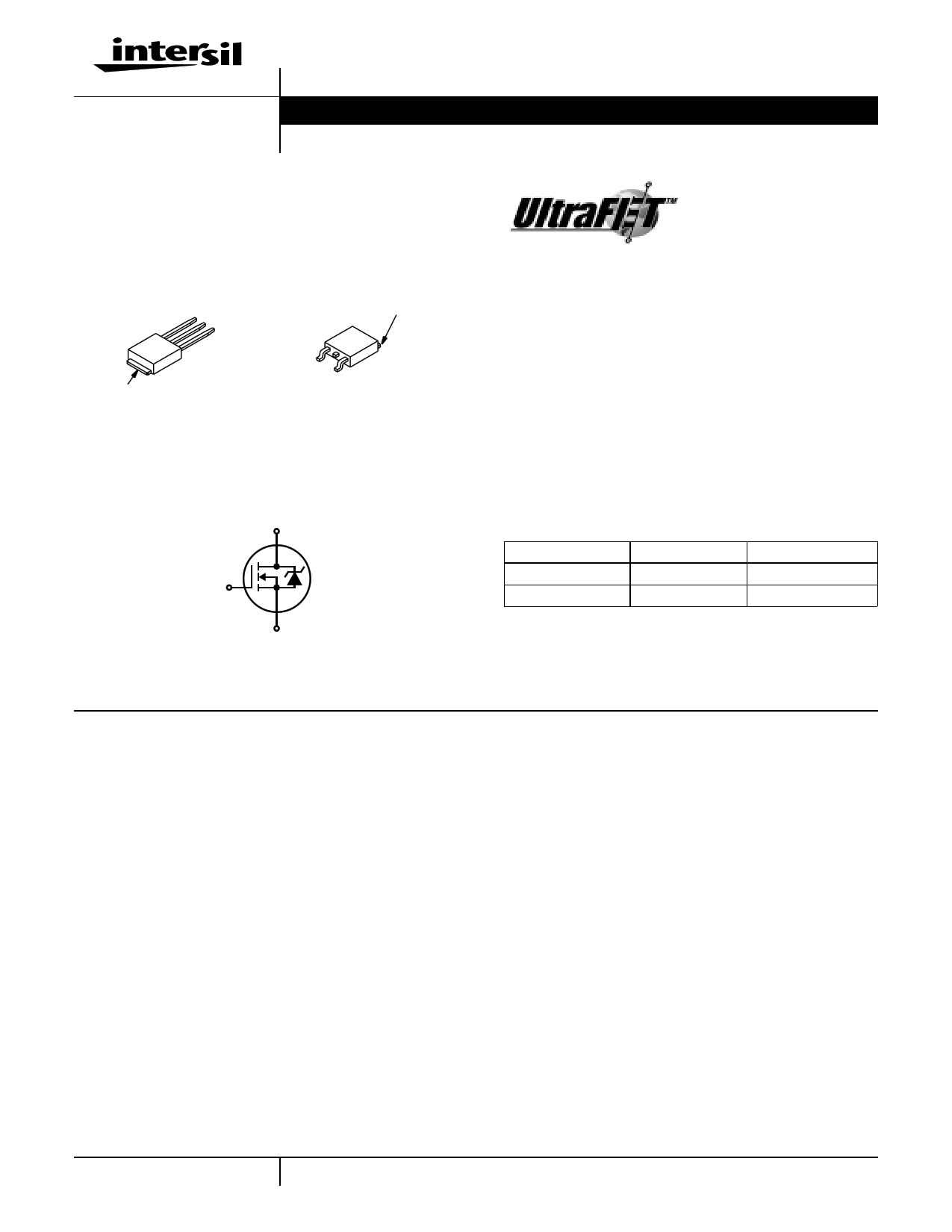
14A, 150V, 0.150 Ohm, N-Channel,
UltraFET Power MOSFET
Packaging
JEDEC TO-251AA
JEDEC TO-252AA
SOURCE
DRAIN
GATE
DRAIN
(FLANGE)
DRAIN
(FLANGE)
HUF75823D3
GATE
SOURCE
HUF75823D3S
Symbol
D
G
S
HUF75823D3, HUF75823D3S
April 2000
File Number 4847
Features
• Ultra Low On-Resistance
- rDS(ON) = 0.150Ω, VGS = 10V
• Simulation Models
- Temperature Compensated PSPICE™ and SABER©
Electrical Models
- Spice and SABER© Thermal Impedance Models
- www.intersil.com
• Peak Current vs Pulse Width Curve
• UIS Rating Curve
Ordering Information
PART NUMBER
PACKAGE
BRAND
HUF75823D3
TO-251AA
75823D
HUF75823D3S
TO-252AA
75823D
NOTE: When ordering, use the entire part number. Add the suffix T
to obtain the variant in tape and reel, e.g., HUF75823D3ST.
Absolute Maximum Ratings TC = 25oC, Unless
Otherwise Specified
HUF75823D3, HUF75823D3S
UNITS
Drain to Source Voltage (Note 1) . . . . . . . . . . . . . . . . . . . . . . . . . . . . . . . . . . . . . . . . . . . VDSS
Drain to Gate Voltage (RGS = 20kΩ) (Note 1) . . . . . . . . . . . . . . . . . . . . . . . . . . . . . . . . . VDGR
Gate to Source Voltage . . . . . . . . . . . . . . . . . . . . . . . . . . . . . . . . . . . . . . . . . . . . . . . . . . . .VGS
Drain Current
Continuous
Continuous
(TC=
(TC=
2150o0CoC, V, VGGSS==101V0V) )(F(Figiugruere2)2).
.
.
.
.
.
.
.
.
.
.
.
.
.
.
.
.
.
.
.
.
.
.
.
.
.
.
.
.
.
.
.
.
.
.
.
.
.
.
.
.
.
.
.
.
.
.
.
.
.
.
.
.
.
.
.
.
.
.
.
.
ID
ID
Pulsed Drain Current . . . . . . . . . . . . . . . . . . . . . . . . . . . . . . . . . . . . . . . . . . . . . . . . . . . . IDM
Pulsed Avalanche Rating . . . . . . . . . . . . . . . . . . . . . . . . . . . . . . . . . . . . . . . . . . . . . . . . . . UIS
150
150
±20
14
10
Figure 4
Figures 6, 14, 15
V
V
V
A
A
Power Dissipation . . . . . . . . . . . . . . . . . . . . . . . . . . . . . . . . . . . . . . . . . . . . . . . . . . . . . . . . .PD
Derate Above 25oC . . . . . . . . . . . . . . . . . . . . . . . . . . . . . . . . . . . . . . . . . . . . . . . . . . . . . . . .
85
0.57
W
W/oC
Operating and Storage Temperature . . . . . . . . . . . . . . . . . . . . . . . . . . . . . . . . . . . . . . TJ, TSTG
-55 to 175
oC
Maximum Temperature for Soldering
Leads at 0.063in (1.6mm) from Case for 10s. . . . . . . . . . . . . . . . . . . . . . . . . . . . . . . . . . . TL
Package Body for 10s, See Techbrief TB334 . . . . . . . . . . . . . . . . . . . . . . . . . . . . . . . . . Tpkg
300
260
oC
oC
NOTES:
1. TJ = 25oC to 150oC.
CAUTION: Stresses above those listed in “Absolute Maximum Ratings” may cause permanent damage to the device. This is a stress only rating and operation of the
device at these or any other conditions above those indicated in the operational sections of this specification is not implied.
1 CAUTION: These devices are sensitive to electrostatic discharge. Follow proper ESD Handling Procedures.
UltraFET™ is a trademark of Intersil Corporation. PSPICE® is a registered trademark of MicroSim Corporation.
1-888-INTERSIL or 321-724-7143 | Intersil and Design is a trademark of Intersil Corporation. | Copyright © Intersil Corporation 2000
1 page 
HUF75823D3, HUF75823D3S
Typical Performance Curves (Continued)
1.2
ID = 250µA
1.1
1.0
3000
1000
100
COSS ≅ CDS + CGD
VGS = 0V, f = 1MHz
CISS = CGS + CGD
CRSS = CGD
0.9
-80
-40 0
40 80 120 160
TJ, JUNCTION TEMPERATURE (oC)
200
FIGURE 11. NORMALIZED DRAIN TO SOURCE BREAKDOWN
VOLTAGE vs JUNCTION TEMPERATURE
10
VDD = 75V
8
100.1
1.0 10
VDS, DRAIN TO SOURCE VOLTAGE (V)
100
FIGURE 12. CAPACITANCE vs DRAIN TO SOURCE VOLTAGE
6
4
WAVEFORMS IN
2 DESCENDING ORDER:
ID = 14A
ID = 7A
0
0 5 10 15 20 25
Qg, GATE CHARGE (nC)
NOTE: Refer to Intersil Application Notes AN7254 and AN7260.
FIGURE 13. GATE CHARGE WAVEFORMS FOR CONSTANT GATE CURRENT
Test Circuits and Waveforms
VARY tP TO OBTAIN
REQUIRED PEAK IAS
VGS
tP
0V
RG
VDS
L
DUT
+
VDD
-
IAS
0.01Ω
FIGURE 14. UNCLAMPED ENERGY TEST CIRCUIT
tP
IAS
BVDSS
VDS
VDD
0
tAV
FIGURE 15. UNCLAMPED ENERGY WAVEFORMS
5
5 Page 
HUF75823D3, HUF75823D3S
TO-251AA
3 LEAD JEDEC TO-251AA PLASTIC PACKAGE
EA
H1 b2
D
A1
TERM. 4
SEATING
PLANE
L1
L
b
b1
12
e
e1
3
c
J1
INCHES
MILLIMETERS
SYMBOL MIN MAX MIN MAX NOTES
A
0.086
0.094
2.19
2.38
-
A1
0.018
0.022
0.46
0.55
3, 4
b
0.028
0.032
0.72
0.81
3, 4
b1
0.033
0.045
0.84
1.14
3
b2
0.205
0.215
5.21
5.46
3, 4
c
0.018
0.022
0.46
0.55
3, 4
D
0.270
0.295
6.86
7.49
-
E
0.250
0.265
6.35
6.73
-
e 0.090 TYP
2.28 TYP
5
e1 0.180 BSC
4.57 BSC
H1
0.035
0.045
0.89
1.14
J1
0.040
0.045
1.02
1.14
L
0.355
0.375
9.02
9.52
5
-
6
-
L1
0.075
0.090
1.91
2.28
2
NOTES:
1. These dimensions are within allowable dimensions of Rev. C of
JEDEC TO-251AA outline dated 9-88.
2. Solder finish uncontrolled in this area.
3. Dimension (without solder).
4. Add typically 0.002 inches (0.05mm) for solder plating.
5. Position of lead to be measured 0.250 inches (6.35mm) from bot-
tom of dimension D.
6. Position of lead to be measured 0.100 inches (2.54mm) from bot-
tom of dimension D.
7. Controlling dimension: Inch.
8. Revision 3 dated 1-00.
All Intersil semiconductor products are manufactured, assembled and tested under ISO9000 quality systems certification.
Intersil semiconductor products are sold by description only. Intersil Corporation reserves the right to make changes in circuit design and/or specifications at any time with-
out notice. Accordingly, the reader is cautioned to verify that data sheets are current before placing orders. Information furnished by Intersil is believed to be accurate and
reliable. However, no responsibility is assumed by Intersil or its subsidiaries for its use; nor for any infringements of patents or other rights of third parties which may result
from its use. No license is granted by implication or otherwise under any patent or patent rights of Intersil or its subsidiaries.
For information regarding Intersil Corporation and its products, see web site www.intersil.com
Sales Office Headquarters
NORTH AMERICA
Intersil Corporation
P. O. Box 883, Mail Stop 53-204
Melbourne, FL 32902
TEL: (321) 724-7000
FAX: (321) 724-7240
EUROPE
Intersil SA
Mercure Center
100, Rue de la Fusee
1130 Brussels, Belgium
TEL: (32) 2.724.2111
FAX: (32) 2.724.22.05
ASIA
Intersil (Taiwan) Ltd.
7F-6, No. 101 Fu Hsing North Road
Taipei, Taiwan
Republic of China
TEL: (886) 2 2716 9310
FAX: (886) 2 2715 3029
11
11 Page | ||
| Páginas | Total 11 Páginas | |
| PDF Descargar | [ Datasheet HUF75925D3ST.PDF ] | |
Hoja de datos destacado
| Número de pieza | Descripción | Fabricantes |
| HUF75925D3ST | 11A/ 200V/ 0.275 Ohm/ N-Channel/ UltraFET Power MOSFETs | Fairchild Semiconductor |
| Número de pieza | Descripción | Fabricantes |
| SLA6805M | High Voltage 3 phase Motor Driver IC. |
Sanken |
| SDC1742 | 12- and 14-Bit Hybrid Synchro / Resolver-to-Digital Converters. |
Analog Devices |
|
DataSheet.es es una pagina web que funciona como un repositorio de manuales o hoja de datos de muchos de los productos más populares, |
| DataSheet.es | 2020 | Privacy Policy | Contacto | Buscar |