|
|
|
PDF ADE7756EB Data sheet ( Hoja de datos )
| Número de pieza | ADE7756EB | |
| Descripción | Evaluation Board Documentation AD7756 Energy metering IC | |
| Fabricantes | Analog Devices | |
| Logotipo | ||
Hay una vista previa y un enlace de descarga de ADE7756EB (archivo pdf) en la parte inferior de esta página. Total 15 Páginas | ||
|
No Preview Available !
PRELIMINARYTECHNICALDATA
=
EvaluationBoardDocumentation
AD7756EnergymeteringIC
PreliminaryTechnicalData
EVAL-ADE7756EB
FEATURES
Evaluation Board is designed to be used together with
accompanying software to implement a fully functional
Energy Meter (Watt-Hour Meter).
Easy connection of various external transducers via
screw terminals.
Easy modification of signal conditioning components
using PCB sockets.
LED indicators on logic outputs CF, ZX, SAG and IRQ.
Optically isolated data output connection to PC parallel port.
Optically isolated frequency output (CF) to BNC.
External Reference option available for
on-chip reference evaluation.
GENERAL DESCRIPTION
The ADE7756 is a high accuracy electrical power mea-
surement IC with a serial interface and a pulse output.
The ADE7756 incorporates two second order sigma delta
ADCs, reference circuitry, temperature sensor and all the
signal processing required to perform active power and
energy measurement.
This documentation describes the ADE7756 evaluation kit
Hardware and Software functionality. The ADE7756
evaluation board, together with the ADE7756 data sheet
and this documentation provides a complete evaluation
platform for the ADE7756.
The evaluation board has been designed so that the
ADE7756 can be evaluated in the end application, i.e.,
Watt-Hour Meter. Using the appropriate transducers on
the current channel (e.g., shunt, CT etc.) the evaluation
board can be connected to a test bench or high voltage
(240V rms) test circuit. An on-board resistor divider
network provides the attenuation for the line voltage. This
application note also describes how the current transducers
should be connected for the best performance.
The evaluation board (watt-hour meter) is configured and
calibrated via the parallel port of a PC. The data interface
between the evaluation board and the PC is fully isolated.
WindowsTM based software is provided with the evaluation
board which allows it to be quickly configured as an
energy meter.
The evaluation board also functions as a stand alone
evaluation system which can be easily incorporated into an
existing system via a 25 way D-Sub connector.
The evaluation board requires two external 5V power
supplies (one is required for isolation purposes) and the
appropriate current transducer.
FUNCTIONAL BLOCK DIAGRAM
V1P
V1N
AGND
AGND AVDD
DVDD DGND +5V
V+ V-
Filter
Network
ADE7756
74HC08
DOUT
SCLK
DIN
CS
RESET
V2N
V2P
Filter
Network
&
Attenuation
Optional External AD780
2.5V Reference
PROTOTYPE
AREA
74HC08
BNC
External
Clock in
Isolated Frequency
output
BNC
CF
CF ZX SAG IRQ
Connector to
PC Parallel
Port
REV. PrB 01/01
Information furnished by Analog Devices is believed to be accurate and
reliable. However, no responsibility is assumed by Analog Devices for its
use, nor for any infringements of patents or other rights of third parties
which may result from its use. No license is granted by implication or
otherwise under any patent or patent rights of Analog Devices.
One Technology Way, P.O. Box 9106, Norwood. MA 02062-9106, U.S.A.
Tel: 617/329-4700
Fax: 617/326-8703
1 page 
PRELIMINARYTECHNICALDATA
PRELIMINARY TECHNICAL DATA
EVAL-ADE7756EB
JP2 JP15
JP4
JP25
JP1
JP3
JP20
AD7756
JP10
JP7
JP8
JP9
JP51
JP13
JP11
JP21
JP14
AB
JP5
JP6
JP19
JP12
AB
Figure 5 - ADE7756 evaluation board jumper positions
SETTING UP THE ADE7756 EVALUATION BOARD
Shown below is a typical set up for the ADE7756 evalua-
tion board. In this example a kWh meter for a 3 wire,
single phase distribution system is shown. For a more
detailed description on how to use a CT as a current
transducer see the Current Sense Inputs section of this docu-
mentation. The line voltage is connected directly to the
evaluation board as shown. Note JP7 should be left open
to ensure that the attenuation network is not bypassed.
Also note the use of two power supplies. The second
power supply is used to power the optical isolation. With
JP14 left open, this will ensure that there is no electrical
connection between the high voltage test circuit and the
PC. The power supplies should have floating voltage
outputs.
The evaluation board is connected to the PC parallel port
using the cable supplied. The cable length should not
exceed 6 feets (2 meters) or the serial communication
between the PC and the evaluation board may become
unpredictable and error prone.
When the evaluation board has been powered up and is
connected to the PC, the supplied software can be
launched. The software will automatically start in energy
meter mode. The next section describes the ADE7756
evaluation software in detail and how it can be installed
and uninstalled.
5.000 V
-
+
5.000 V
-
+
110V
10A
10A
110V
V+ V-
1:2000
CT
SK2
2.5Ω
SH1A
AGND
SH1B
2.5Ω
SK1
25mV
SK4
V1P
V1N
JP1 = Open
JP2 = Open
JP3 = Open
JP4 = Open
JP5 = B
JP6 = B
25mV
JP9
JP7 = Open JP13 = Open
JP8 = Open JP14 = Open
JP9 = Open JP15 = Closed
JP10 = Closed JP19 = B
JP11 = Closed JP20 = Closed
JP12 = B
JP21 = Closed
JP25 = Closed
R57
1kΩ
JP10
V2N
C54
33nF
450mV
JP7
220V
R53
255kΩ
JP8
R54
255kΩ
C53
33nF
V2P
1kΩ
1.0666 Hz
SK5
BNC2
To PC
Parallel Port
Load Load
110V
REV. PrB 01/01
Figure 6 - Typical set up for the ADE7756 evaluation board
–5–
5 Page 
PRELIMINARYTECHNICALDATA
PRELIMINARY TECHNICAL DATA
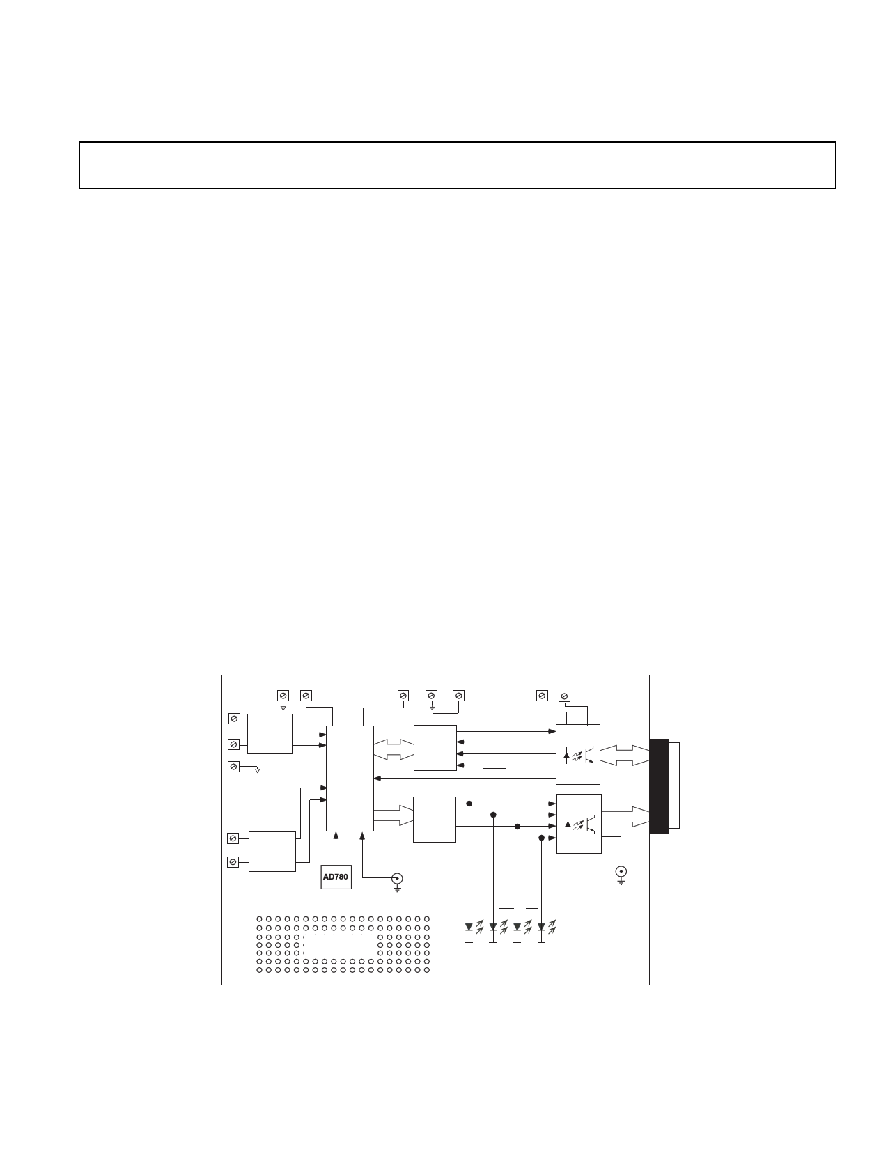
Evaluationboardschematic(rev.C)
EVAL-ADE7756EB
REV. PrB 01/01
–11–
11 Page | ||
| Páginas | Total 15 Páginas | |
| PDF Descargar | [ Datasheet ADE7756EB.PDF ] | |
Hoja de datos destacado
| Número de pieza | Descripción | Fabricantes |
| ADE7756EB | Evaluation Board Documentation AD7756 Energy metering IC | Analog Devices |
| Número de pieza | Descripción | Fabricantes |
| SLA6805M | High Voltage 3 phase Motor Driver IC. |
Sanken |
| SDC1742 | 12- and 14-Bit Hybrid Synchro / Resolver-to-Digital Converters. |
Analog Devices |
|
DataSheet.es es una pagina web que funciona como un repositorio de manuales o hoja de datos de muchos de los productos más populares, |
| DataSheet.es | 2020 | Privacy Policy | Contacto | Buscar |