|
|
|
PDF ADDS-21XX-SW-SUN Data sheet ( Hoja de datos )
| Número de pieza | ADDS-21XX-SW-SUN | |
| Descripción | ADSP-2100 Family Development Tools | |
| Fabricantes | Analog Devices | |
| Logotipo | ||
Hay una vista previa y un enlace de descarga de ADDS-21XX-SW-SUN (archivo pdf) en la parte inferior de esta página. Total 16 Páginas | ||
|
No Preview Available !
a
ADSP-2100 Family
Development Tools
ADDS-21xx-TOOLS
FEATURES
DEVELOPMENT SOFTWARE TOOLS
SYSTEM BUILDER
Defines Architecture of ADSP-21xx System
Specifies Amount of RAM/ROM Memory
ASSEMBLER
Easy-to-Program, Algebraic Instruction Syntax
Supports C Language Constructs
Provides Flexible Macro Processing
Encourages Modular Code Development
LINKER
Maps Assembler Output to Target System Memory
Supports User-Defined Library Routines
Creates Memory Map Listing
PROM SPLITTER & HOST PROCESSOR PORT (HIP)
SPLITTER
Generates PROM Programmer Compatible Files in
a Variety of Industry-Standard Formats
Formats Executable File for Programming PROMs or
for Host Processor Booting
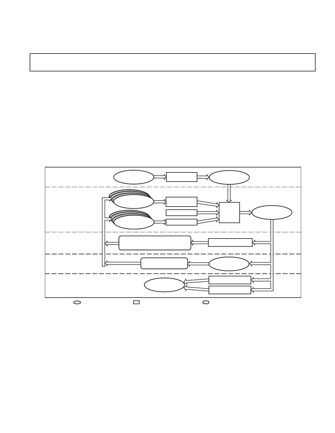
SYSTEM DEVELOPMENT PROCESS OVERVIEW
STEP 1:
DESCRIBE
ARCHITECTURE
SYSTEM
SPECIFICATION
FILE
SYSTEM
BUILDER
SYSTEM
ARCHITECTURE
FILE
STEP 2:
GENERATE
CODE
STEP 3:
DEBUG
SOFTWARE
STEP 4:
DEBUG IN TARGET
SYSTEM
STEP 5:
MANUFACTURE
FINAL SYSTEM
C SOURCE
FILES
ASSEMBLER
SOURCE
FILES
ANSI
C COMPILER
LIBRARIES
ASSEMBLER
EZ-LAB DEVELOPMENT BOARD
OR
THIRD-PARTY PC PLUG-IN CARDS
EZ-ICE EMULATOR
TESTED &
DEBUGGED
DSP BOARD
= USER FILE OR HARDWARE
= SOFTWARE DEVELOPMENT TOOL
LINKER
EXECUTABLE
FILE
SOFTWARE SIMULATOR
TARGET
BOARD
PROM SPLITTER
HIP SPLITTER
= HARDWARE DEVELOPMENT TOOL
REV. B
Information furnished by Analog Devices is believed to be accurate and
reliable. However, no responsibility is assumed by Analog Devices for its
use, nor for any infringements of patents or other rights of third parties
which may result from its use. No license is granted by implication or
otherwise under any patent or patent rights of Analog Devices.
© Analog Devices, Inc., 1995
One Technology Way, P.O. Box 9106, Norwood. MA 02062-9106, U.S.A.
Tel: 617/329-4700
Fax: 617/326-8703
1 page 
EZ-KIT Lite - Monitor
File View Demo Loading Options Help
? PD P D
List of Demos
DTNF
Filter
Echo Canceller
ADPCM
7.8 kbs LPC
2.4 kbs LPC
Exit App
ADDS-21xx-TOOLS
Ready
Figure 1. EZ-KIT Lite Monitor Software
SIMULATORS
There is a simulator for each ADSP-2100 Family processor that
provides instruction-level simulation of program execution. The
Simulator models system memory and I/O according to the
contents of the system architecture file, and provides windows
to display different portions of the target system hardware. The
Graphical User Interface (GUI) lets system designers inter-
actively observe and alter register and memory contents,
providing a powerful debug environment. Simulator commands
can be entered from the mouse or keyboard.
Features offered by the ADSP-2100 Family Simulators include
the following:
• Program and Data Memory Simulation
• Memory-Mapped I/O Port Simulation
• Interrupt Simulation
• Program Booting (from PROM or host processor) Simulation
• Code Execution Pattern Profiling for Program Optimization
• On-Line Help
• Reconfigurable Windows
• Same User Interface as EZ-ICE Emulators
CBUG C SOURCE-LEVEL DEBUGGER
The Simulators are seamlessly integrated with the CBUG C
source-level debugger. CBUG supports the following
operations:
• Run, Step, Next, and Finish Program Execution Commands
• C Source Code Breakpoints
• Local and Global Variable Display with Auto Refresh
Examines Value of Variables at Previously Executed
Instructions
• Symbol Look-Up
HARDWARE TOOLS
EZ-KIT Lite
The ADSP-21xx EZ-KIT Lite is a low-cost, easy to use
development platform on which you can quickly get started with
your ADSP-2100 Family based DSP software design. The EZ-
KIT Lite is a complete development system package that
includes:
• ADDS-2181 EZ-LAB Board
• MS-Windows 3.1 Based Monitor Software
• Development Software Kit (upgradable to complete ADSP-
2100 Family Development Software package for full-featured
development of final systems)
• Demo Programs
- Digital Filtering
- Speech Compression
- FFT
- Echo Cancellation
- DTMF Tone Generation
- MPEG Audio Playback
The EZ-Kit Lite uses the ADDS-2181 EZ-LAB as a
development platform on which you can develop software
applications for any of the ADSP-2100 Family DSPs. This is
possible because the ADSP-2181 represents a superset of the
features of the ADSP-2101/2105/2111/2115/2171 processors.
With the ADSP-2181’s 32K words of on-chip RAM, there is no
need for additional RAM devices on the EZ-LAB board. The
board simply requires connection to power, an analog input
source, and amplified speakers to be able to run audio
applications and demos.
The EZ-LAB board can run in a stand-alone mode, or it can be
connected to the RS-232 port of your PC. A Windows-based
monitor program lets you interactively download programs and
interrogate the ADSP-2181 (see Figure 1). The board comes
with a socketed EPROM so that you can run the monitor
program or demonstrations provided—or you can plug in an
EPROM containing your own code.
REV. B
–5–
5 Page 
ADDS-21xx-TOOLS
GUI Interface
EZ-ICE software uses a Graphical User Interface (GUI) to
increase development productivity by making your data easier to
view and manipulate—without switching between screens—
when debugging. In addition, you can obtain on-line help for
the currently selected window. The GUI user interface design is
the same one used with the ADSP-2100 Family Simulator
software, making both tools easier to use.
Clock Speed
EZ-ICE runs at full speed. There is no degradation of
processor performance other than BR, BG, and RESET, which
are slightly delayed. A jumper is used to select either the target
system clock or the EZ-ICE clock. The oscillator socket lets you
use other oscillator devices to achieve different clock speeds.
Memory
The ADSP-2101, ADSP-2111, and ADSP-2171 EZ-ICE each
have 8K × 24-bit overlay program memory and 16K × 16-bit
overlay data memory. You can either run programs from target
system memory, emulator overlay memory, or from a combination
of both. The overlay memory option is jumper-selectable.
Additional Equipment Required
EZ-ICE requires a +5 V dc power supply capable of supplying
1 A of current.
3-Volt Emulation
The 3-Volt Emulation Converter Board may be used with the
ADSP-2101 EZ-ICE to enable emulation of ADSP-2103 (3 V)
systems.
SURFACE MOUNT ADAPTORS
ADSP-2101/ADSP-2105/ADSP-2115
Several surface mount adaptors are available for emulation of
the ADSP-2101. For example: for the 68-pin PLCC package of
the ADSP-2101 and ADSP-2105, a PGA-to-PLCC adaptor is
available from the vendors listed at the end of this data sheet.
For the 80-pin PQFP package of the ADSP-2101, a 68-pin
PGA to 80-pin PQFP adaptor is also available.
The ADDS-2101-PGA/PQFP, a surface-mountable PGA-to-
PQFP adaptor, provides a footprint that exactly matches the 80-
pin package. This solution does not require extra space around
the adaptor or an extra through hole to the PQFP package to let
you use the same PCB in production. The PGA-to-PQFP
adaptor is surface mounted in the usual manner, and the PGA
connector of the ADSP-2101 EZ-ICE or ICE can be directly
plugged in.
ADSP-2111
The ADDS-2100-PGA/PQFP, a surface-mountable 101-pin
PGA to 100-pin PQFP adaptor, matches the ADSP-2111
package footprints. This solution does not require extra space
around the adaptor, and you can use the same PCB in
production. The PGA-to-PQFP adaptor is surface mounted in
the usual manner, and the PGA connector of the ADSP-2111
EZ-ICE can be directly plugged in.
ADSP-2171
The ADSP-2171 EZ-ICE Emulator is designed for compatibil-
ity with the surface mountable 128-pin PQFP package using an
adaptor card which plugs onto the ADDS-21xx EZ-ICE board
and then snaps onto the PQFP chip. This is illustrated in Figure
3. Extra space should be allowed around the PQFP chip to
allow clearance for the adaptor.
An alternate approach is required for the TQFP chip package.
Because of the extremely low profile of the surface mount
TQFP package, it is not practical to use a snap-on adaptor or
probe. Thus, in order to use the EZ-ICE, it is necessary to
provide a pair of header connectors on the target board that the
ADDS-21xx EZ-ICE board can plug directly onto. Extra space
around the adaptor and extra through-holes to the PQFP
package are not required to let you use the same PCB in
production. Dimensional requirements for placing the headers
is also shown in Figure 2.
ADSP-2181
There is no need for a surface mount adaptor for the ADSP-
2181 EZ-ICE. Instead, the ICE-Port Emulator Interface allows
for a simple 14-pin connector interface between the target board
and the EZ-ICE.
DESIGNING AN EZ-ICE COMPATIBLE TARGET
SYSTEM FOR THE ADSP-2181 AND THE ADSP-2171
ADSP-2181 Target System Requirements
The ADSP-2181 has on-chip emulation support and a special
set of pins that interface to the EZ-ICE called the ICE-Port.
The ICE-Port allows in-circuit emulation without replacing the
target system’s processor or overriding it with a probe, requiring
only a simple 14-pin header connector to interface to the EZ-
ICE (see Figure 3).
Table IV lists the pins and functions used in the ADSP-2181’s
ICE-Port emulation interface.
Table IV. ADSP-2181 ICE-Port Emulation Interface
Pin Description
BR Bus Request
BG Bus Grant
RESET
Reset
GND
Ground
EBR Emulator Bus Request (emulator-only*)
EBG
Emulator Bus Grant (emulator-only*)
ERESET
Emulator Reset (emulator-only*)
EMS
Emulator Memory Space (emulator-only*)
EINT
Emulator Interrupt Request (emulator-only*)
ECLK
Emulator Clock (emulator-only*)
ELIN
Emulator Data In (emulator-only*)
ELOUT
Emulator Data Out (emulator-only*)
EE Emulator Enable (emulator-only*)
NOTE
*These ADSP-2181 pins must be connected only to the ICE-Port connector in
the target system. These pins have no function except during emulation. Keep
all traces as short as possible; no longer than 3 inches.
REV. B
–11–
11 Page | ||
| Páginas | Total 16 Páginas | |
| PDF Descargar | [ Datasheet ADDS-21XX-SW-SUN.PDF ] | |
Hoja de datos destacado
| Número de pieza | Descripción | Fabricantes |
| ADDS-21XX-SW-SUN | ADSP-2100 Family Development Tools | Analog Devices |
| Número de pieza | Descripción | Fabricantes |
| SLA6805M | High Voltage 3 phase Motor Driver IC. |
Sanken |
| SDC1742 | 12- and 14-Bit Hybrid Synchro / Resolver-to-Digital Converters. |
Analog Devices |
|
DataSheet.es es una pagina web que funciona como un repositorio de manuales o hoja de datos de muchos de los productos más populares, |
| DataSheet.es | 2020 | Privacy Policy | Contacto | Buscar |