|
|
|
PDF ACS373D Data sheet ( Hoja de datos )
| Número de pieza | ACS373D | |
| Descripción | Radiation Hardened Octal Transparent Latch/ Three-State | |
| Fabricantes | Intersil Corporation | |
| Logotipo | ||
Hay una vista previa y un enlace de descarga de ACS373D (archivo pdf) en la parte inferior de esta página. Total 10 Páginas | ||
|
No Preview Available !
ACS373MS
April 1995
Radiation Hardened
Octal Transparent Latch, Three-State
Features
• 1.25 Micron Radiation Hardened SOS CMOS
• Total Dose 300K RAD (Si)
• Single Event Upset (SEU) Immunity
<1 x 10⁻¹⁰ Errors/Bit-Day (Typ)
• SEU LET Threshold >80 MEV-cm2/mg
• Dose Rate Upset >1011 RAD (Si)/s, 20ns Pulse
• Latch-Up Free Under Any Conditions
• Military Temperature Range: -55oC to +125oC
• Significant Power Reduction Compared to ALSTTL Logic
• DC Operating Voltage Range: 4.5V to 5.5V
• Input Logic Levels
- VIL = 30% of VCC Max
- VIH = 70% of VCC Min
• Input Current ≤1µA at VOL, VOH
Description
The Intersil ACS373MS is a radiation hardened octal transparent
latch with three-state outputs. The outputs are transparent to the
inputs when the latch enable (LE) is high. When the LE goes low,
the data is latched. When the Output Enable (OE) is high, the
outputs are in the high impedance state. The latch operation is
independent of the state of the output enable.
The ACS373MS utilizes advanced CMOS/SOS technology to
achieve high-speed operation. This device is a member of the
radiation hardened, high-speed, CMOS/SOS Logic Family.
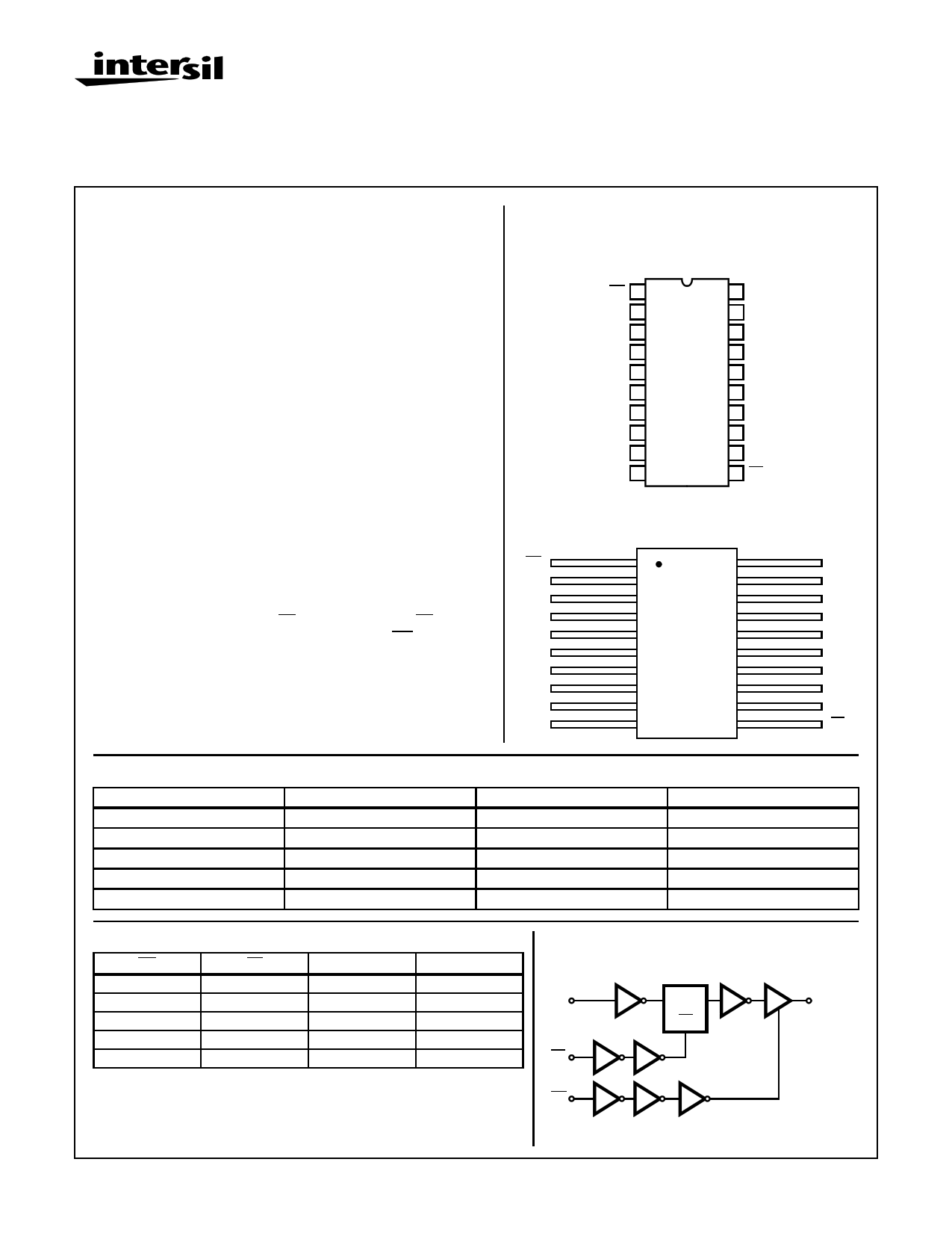
Pinouts
20 LEAD CERAMIC DUAL-IN-LINE
MIL-STD-1835 DESIGNATOR, CDIP2-T20, LEAD FINISH C
TOP VIEW
OE 1
Q0 2
D0 3
D1 4
Q1 5
Q2 6
D2 7
D3 8
Q3 9
GND 10
20 VCC
19 Q7
18 D7
17 D6
16 Q6
15 Q5
14 D5
13 D4
12 Q4
11 LE
20 LEAD CERAMIC FLATPACK
MIL-STD-1835 DESIGNATOR, CDFP4-F20, LEAD FINISH C
TOP VIEW
OE
Q0
D0
D1
Q1
Q2
D2
D3
Q3
GND
1 20
2 19
3 18
4 17
5 16
6 15
7 14
8 13
9 12
10 11
VCC
Q7
D7
D6
Q6
Q5
D5
D4
Q4
LE
Ordering Information
PART NUMBER
ACS373DMSR
ACS373KMSR
ACS373D/Sample
ACS373K/Sample
ACS373HMSR
TEMPERATURE RANGE
-55oC to +125oC
-55oC to +125oC
+25oC
+25oC
+25oC
SCREENING LEVEL
Intersil Class S Equivalent
Intersil Class S Equivalent
Sample
Sample
Die
PACKAGE
20 Lead SBDIP
20 Lead Ceramic Flatpack
20 Lead SBDIP
20 Lead Ceramic Flatpack
Die
Truth Table
OE LE
D
Q
L HHH
LHL L
LL I L
L L hH
HXXZ
NOTE:
L = Low Voltage Level
H = High Voltage Level
X = Don’t Care
Z = High Impedance State
I = Low voltage level one set-up time prior to the high to low latch enable transition
h = High voltage level one set-up time prior to the high to low latch enable transition
Functional Diagram
1 OF 8
(3, 4, 7, 8, 13,
14, 17, 18)
D
LATCH
DQ
COMMON
CONTROLS
LE
LE
(11)
OE
(1)
OE
Q
(2, 5, 6, 9, 12,
15, 16, 19)
CAUTION: These devices are sensitive to electrostatic discharge; follow proper IC Handling Procedures.
1-888-INTERSIL or 321-724-7143 | Copyright © Intersil Corporation 1999
1
Spec Number 518799
File Number 3999
1 page 
Specifications ACS373MS
TABLE 6. APPLICABLE SUBGROUPS
CONFORMANCE GROUPS
METHOD
GROUP A SUBGROUPS
Initial Test (Preburn-In)
100%/5004
1, 7, 9
Interim Test 1 (Postburn-In)
100%/5004
1, 7, 9
Interim Test 2 (Postburn-In)
100%/5004
1, 7, 9
PDA
100%/5004
1, 7, 9, Deltas
Interim Test 3 (Postburn-In)
100%/5004
1, 7, 9
PDA
100%/5004
1, 7, 9, Deltas
Final Test
100%/5004
2, 3, 8A, 8B, 10, 11
Group A (Note 1)
Sample/5005
1, 2, 3, 7, 8A, 8B, 9, 10, 11
Group B
Subgroup B-5
Sample/5005 1, 2, 3, 7, 8A, 8B, 9, 10, 11, Deltas
Subgroup B-6
Sample/5005
1, 7, 9
Group D
Sample/5005
1, 7, 9
NOTE:
1. Alternate Group A testing may be exercised in accordance with MIL-STD-883, Method 5005.
READ AND RECORD
ICC, IOL/H, IOZL/H
ICC, IOL/H, IOZL/H
ICC, IOL/H, IOZL/H
ICC, IOL/H, IOZL/H
Subgroups 1, 2, 3, 9, 10, 11
TABLE 7. TOTAL DOSE IRRADIATION
TEST
CONFORMANCE GROUP METHOD
PRE RAD
POST RAD
Group E Subgroup 2
5005
1, 7, 9
Table 4
NOTE:
1. Except FN test which will be performed 100% Go/No-Go.
READ AND RECORD
PRE RAD
POST RAD
1, 9 Table 4 (Note 1)
TABLE 8. BURN-IN TEST CONNECTIONS (+125oC < TA < 139oC)
OPEN
GROUND
STATIC BURN-IN 1 (Note 1)
- 1, 3, 4, 7, 8, 10, 11,
13, 14, 17, 18
STATIC BURN-IN 2 (Note 1)
- 10
DYNAMIC BURN-IN (Note 1)
-
1, 10
1/2 VCC = 3V ±0.5V
VCC = 6V ±0.5V
2, 5, 6, 9, 12, 15, 16, 19
20
2, 5, 6, 9, 12, 15, 16, 19 1, 3, 4, 7, 8, 11, 13,
14, 17, 18, 20
2, 5, 6, 9, 12, 15, 16, 19
20
NOTE:
1. Each pin except VCC and GND will have a series resistor of 500Ω ±5% for static burn-in.
OSCILLATOR
50kHz
25kHz
--
--
11 3, 4, 7, 8, 13,
14, 17, 18
TABLE 9. IRRADIATION TEST CONNECTIONS (TA = +25oC, ±5oC)
FUNCTION
OPEN
GROUND
VCC = 5V ±0.5V
Irradiation Circuit (Note 1)
2, 5, 6, 9, 12, 15, 16, 19
10 1, 3, 4, 7, 8, 11, 13, 14, 17, 18, 20
NOTE:
1. Each pin except VCC and GND will have a series resistor of 47kΩ ±5%. Group E, Subgroup 2, sample size is 4 dice/wafer, 0 failures.
Spec Number 518799
5
5 Page | ||
| Páginas | Total 10 Páginas | |
| PDF Descargar | [ Datasheet ACS373D.PDF ] | |
Hoja de datos destacado
| Número de pieza | Descripción | Fabricantes |
| ACS373D | Radiation Hardened Octal Transparent Latch/ Three-State | Intersil Corporation |
| ACS373DMSR | Radiation Hardened Octal Transparent Latch/ Three-State | Intersil Corporation |
| ACS373HMSR | Radiation Hardened Octal Transparent Latch/ Three-State | Intersil Corporation |
| ACS373K | Radiation Hardened Octal Transparent Latch/ Three-State | Intersil Corporation |
| Número de pieza | Descripción | Fabricantes |
| SLA6805M | High Voltage 3 phase Motor Driver IC. |
Sanken |
| SDC1742 | 12- and 14-Bit Hybrid Synchro / Resolver-to-Digital Converters. |
Analog Devices |
|
DataSheet.es es una pagina web que funciona como un repositorio de manuales o hoja de datos de muchos de los productos más populares, |
| DataSheet.es | 2020 | Privacy Policy | Contacto | Buscar |