|
|
|
PDF AD1895 Data sheet ( Hoja de datos )
| Número de pieza | AD1895 | |
| Descripción | 192 kHz Stereo Asynchronous Sample Rate Converter | |
| Fabricantes | Analog Devices | |
| Logotipo | ||
Hay una vista previa y un enlace de descarga de AD1895 (archivo pdf) en la parte inferior de esta página. Total 24 Páginas | ||
|
No Preview Available !
a
192 kHz Stereo Asynchronous
Sample Rate Converter
AD1895*
FEATURES
Automatically Senses Sample Frequencies
No Programming Required
Attenuates Sample Clock Jitter
3.3 V–5 V Input and 3.3 V Core Supply Voltages
Accepts 16-/18-/20-/24-Bit Data
Up to 192 kHz Sample Rate
Input/Output Sample Ratios from 7.75:1 to 1:8
Bypass Mode
Multiple AD1895 TDM Daisy-Chain Mode
128 dB Signal-to-Noise and Dynamic Range
(A-Weighted, 20 Hz–20 kHz BW)
Up to –122 dB THD + N
Linear Phase FIR Filter
Hardware Controllable Soft Mute
Supports 256 ؋ fS, 512 ؋ fS or 768 ؋ fS Master Mode
Clock
Flexible Three-Wire Serial Data Port with Left-Justified,
I2S, Right-Justified (16-, 18-, 20-, 24-Bits), and TDM
Serial Port Modes
Master/Slave Input and Output Modes
28-Lead SSOP Plastic Package
APPLICATIONS
Home Theater Systems, Automotive Audio Systems,
DVD, DVD-R, CD-R, Set-Top Boxes, Digital Audio
Effects Processors
PRODUCT OVERVIEW
The AD1895 is a 24-bit, high-performance, single-chip, second-
generation asynchronous sample rate converter. Based upon
Analog Devices, Inc. experience with its first asynchronous
sample rate converter, the AD1890, the AD1895 offers improved
performance and additional features. This improved performance
includes a THD + N range of –115 dB to –122 dB depending
on sample rate and input frequency, 128 dB (A-Weighted)
dynamic range, 192 kHz sampling frequencies for both input and
output sample rates, improved jitter rejection, and 1:8 upsampling
and 7.75:1 downsampling ratios. Additional features include
more serial formats, a bypass mode, and better interfacing to
digital signal processors.
The AD1895 has a 3-wire interface for the serial input and
output ports that supports left-justified, I2S, and right-justified
(16-, 18-, 20-, 24-bit) modes. Additionally, the serial output
port supports TDM mode for daisy chaining multiple AD1895s to
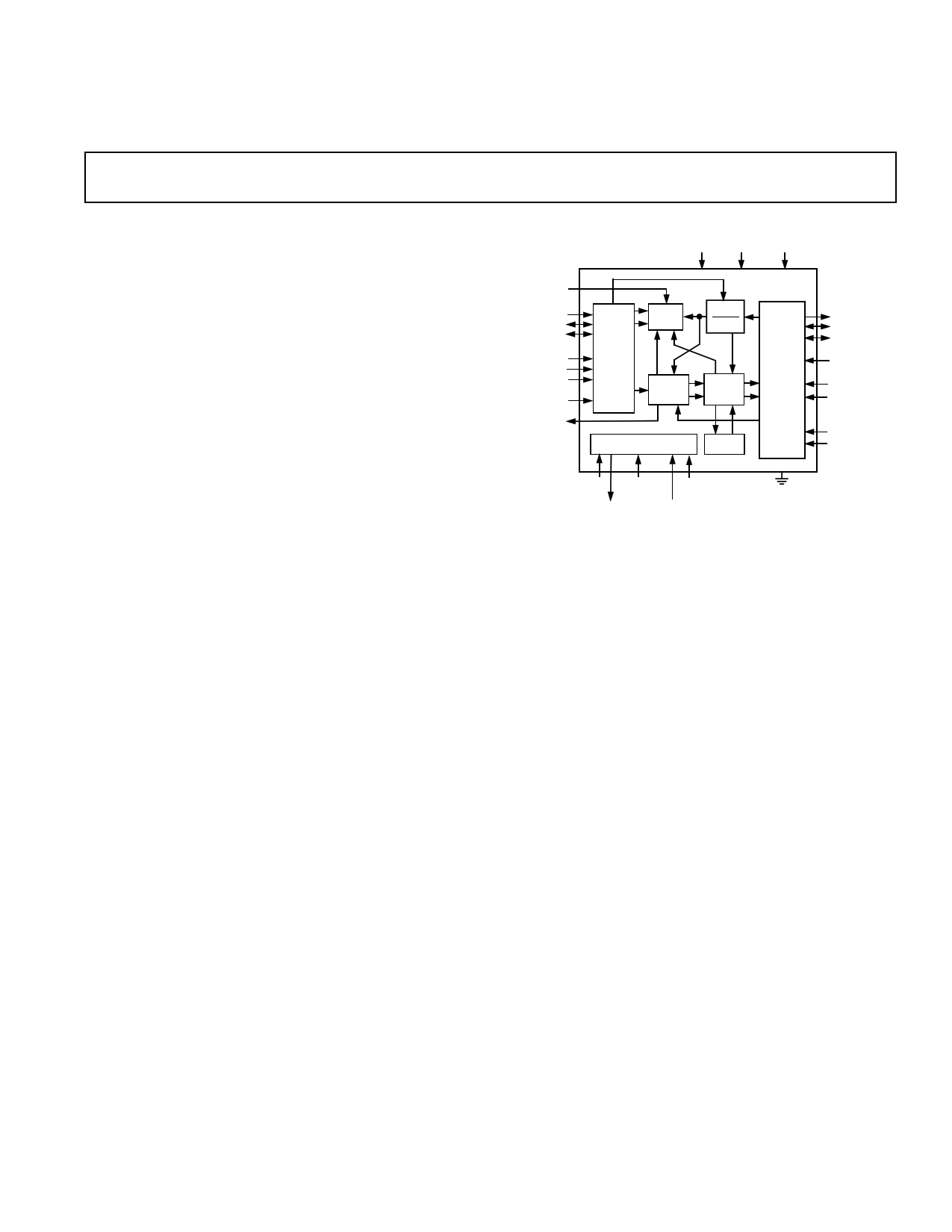
FUNCTIONAL BLOCK DIAGRAM
RESET VDD_IO VDD_CORE
MUTE_I
SDATA_I
SCLK_I
LRCLK_I
SMODE_IN_0
SMODE_IN_1
SMODE_IN_2
BYPASS
MUTE_O
SERIAL
INPUT
FIFO
DIGITAL
PLL
AD1895
FSOUT
FSIN
FIR
FILTER
SERIAL
OUTPUT
SDATA_O
SCLK_O
LRCLK_O
TDM_IN
SMODE_O_0
SMODE_O_1
CLOCK DIVIDER
ROM
WLNGTH_O_0
WLNGTH_O_1
MCLK_I MSMODE_0 MSMODE_2
MCLK_O MSMODE_1
a digital signal processor. The serial output data is dithered down
to 20, 18 or 16 bits when 20-, 18- or 16-bit output data is selected.
The AD1895 sample rate converts the data from the serial input
port to the sample rate of the serial output port. The sample rate
at the serial input port can be asynchronous with respect to the
output sample rate of the output serial port. The master clock to
the AD1895, MCLK, can be asynchronous to both the serial
input and output ports.
MCLK can either be generated off-chip or on-chip by the AD1895
master clock oscillator. Since MCLK can be asynchronous to the
input or output serial ports, a crystal can be used to generate
MCLK internally to reduce noise and EMI emissions on the
board. When MCLK is synchronous to either the output or input
serial port, the AD1895 can be configured in a master mode where
MCLK is divided down and used to generate the left/right
and bit clocks for the serial port that is synchronous to MCLK.
The AD1895 supports master modes of 256 × fS, 512 × fS, and
768 × fS for both input and output serial ports.
Conceptually, the AD1895 interpolates the serial input data by
a rate of 220 and samples the interpolated data stream by the
output sample rate. In practice, a 64-tap FIR filter with 220
polyphases, a FIFO, a digital servo loop that measures the time
difference between input and output samples within 5 ps, and a
digital circuit to track the sample rate ratio are used to perform
the interpolation and output sampling. Refer to the Theory of
Operation section. The digital servo loop and sample rate ratio
circuit automatically track the input and output sample rates.
*Patents pending.
REV. A
Information furnished by Analog Devices is believed to be accurate and
reliable. However, no responsibility is assumed by Analog Devices for its
use, nor for any infringements of patents or other rights of third parties that
may result from its use. No license is granted by implication or otherwise
under any patent or patent rights of Analog Devices.
(Continued on page 15)
One Technology Way, P.O. Box 9106, Norwood, MA 02062-9106, U.S.A.
Tel: 781/329-4700
www.analog.com
Fax: 781/326-8703
© Analog Devices, Inc., 2001
1 page 
POWER SUPPLIES (VDD_CORE = 3.3 V ؎ 5%, VDD_IO = 5.0 V ؎ 10%)
Parameter
Min
Total Active Power Dissipation
48 kHz: 48 kHz
96 kHz: 96 kHz
192 kHz: 192 kHz
Total Power Down Dissipation: (RESET LO)
Specifications subject to change without notice.
Typ
65
85
132
2
AD1895
Max Unit
mW
mW
mW
mW
TEMPERATURE RANGE
Parameter
Specifications Guaranteed
Functionality Guaranteed
Storage
Thermal Resistance, θJA (Junction-to-Ambient)
Specifications subject to change without notice.
Min
–40
–55
Typ Max Unit
25 °C
+105
°C
+150
°C
109 °C/W
ABSOLUTE MAXIMUM RATINGS*
Parameter
Min Max Unit
Power Supplies
VDD_CORE
VDD_IO
Digital Inputs
Input Current
Input Voltage
Ambient Temperature (Operating)
–0.3
–0.3
DGND – 0.3
–40
+3.6 V
+6.0 V
± 10 mA
VDD_IO + 0.3 V
+105
°C
*Stresses greater than those listed under Absolute Maximum Ratings may cause permanent damage to the device. This is a stress rating only; functional operation of the
device at these or any other conditions above those indicated in the operational section of this specification is not implied. Exposure to absolute maximum rating conditions
for extended periods may affect device reliability.
Model
AD1895YRS
AD1895YRSRL
ORDERING GUIDE
Temperature Range
–40°C to +105°C
–40°C to +105°C
Package Description
28-Lead SSOP
28-Lead SSOP
Package Option
RS-28
RS-28 on 13" Reel
CAUTION
ESD (electrostatic discharge) sensitive device. Electrostatic charges as high as 4000 V readily
accumulate on the human body and test equipment and can discharge without detection. Although
the AD1895 features proprietary ESD protection circuitry, permanent damage may occur on
devices subjected to high-energy electrostatic discharges. Therefore, proper ESD precautions are
recommended to avoid performance degradation or loss of functionality.
WARNING!
ESD SENSITIVE DEVICE
REV. A
–5–
5 Page 
–119
–121
–123
–125
–127
–129
–131
–133
–135
30000
55000
80000 105000 130000 155000 180000
OUTPUT SAMPLE RATE – Hz
TPC 25. THD + N vs. Output Sample Rate, fS_IN = 48 kHz,
0 dBFS 1 kHz Tone
AD1895
–119
–121
–123
–125
–127
–129
–131
–133
–135
30000
55000
80000 105000 130000 155000 180000
OUTPUT SAMPLE RATE – Hz
TPC 28. THD + N vs. Output Sample Rate, fS_IN = 96 kHz,
0 dBFS 1 kHz Tone
–119
–121
–123
–125
–127
–129
–131
–133
–135
30000
55000
80000 105000 130000 155000 180000
OUTPUT SAMPLE RATE – Hz
TPC 26. THD + N vs. Output Sample Rate, fS_IN =
44.1 kHz, 0 dBFS 1 kHz Tone
–119
–121
–123
–125
–127
–129
–131
–133
–135
30000
55000
80000 105000 130000 155000 180000
OUTPUT SAMPLE RATE – Hz
TPC 27. THD + N vs. Output Sample Rate, fS_IN = 32 kHz,
0 dBFS 1 kHz Tone
–119
–121
–123
–125
–127
–129
–131
–133
–135
30000
55000
80000 105000 130000 155000 180000
OUTPUT SAMPLE RATE – Hz
TPC 29. DNR vs. Output Sample Rate, fS_IN = 192 kHz,
–60 dBFS 1 kHz Tone
–119
–121
–123
–125
–127
–129
–131
–133
–135
30000
55000
80000 105000 130000 155000 180000
OUTPUT SAMPLE RATE – Hz
TPC 30. DNR vs. Output Sample Rate, fS_IN = 32 kHz,
–60 dBFS 1 kHz Tone
REV. A
–11–
11 Page | ||
| Páginas | Total 24 Páginas | |
| PDF Descargar | [ Datasheet AD1895.PDF ] | |
Hoja de datos destacado
| Número de pieza | Descripción | Fabricantes |
| AD1890 | SamplePort Stereo Asynchronous Sample Rate Converters | Analog Devices |
| AD1891 | SamplePort Stereo Asynchronous Sample Rate Converters | Analog Devices |
| AD1892 | Integrated Digital Receiver/Rate Converter | Analog Devices |
| AD1893 | Low Cost SamplePort 16-Bit Stereo Asynchronous Sample Rate Converter | Analog Devices |
| Número de pieza | Descripción | Fabricantes |
| SLA6805M | High Voltage 3 phase Motor Driver IC. |
Sanken |
| SDC1742 | 12- and 14-Bit Hybrid Synchro / Resolver-to-Digital Converters. |
Analog Devices |
|
DataSheet.es es una pagina web que funciona como un repositorio de manuales o hoja de datos de muchos de los productos más populares, |
| DataSheet.es | 2020 | Privacy Policy | Contacto | Buscar |