|
|
|
PDF ADM1486 Data sheet ( Hoja de datos )
| Número de pieza | ADM1486 | |
| Descripción | 0.8 mA PROFIBUS RS-485 Transceiver | |
| Fabricantes | Analog Devices | |
| Logotipo | ||
Hay una vista previa y un enlace de descarga de ADM1486 (archivo pdf) en la parte inferior de esta página. Total 16 Páginas | ||
|
No Preview Available !
FEATURES
Meets and exceeds EIA RS-485 and EIA RS-422 standards
30 Mbps data rate
Recommended for PROFIBUS applications
2.1 V minimum differential output with 54 Ω termination
Low power 0.8 mA ICC
Thermal shutdown and short-circuit protection
0.5 ns skew driver and receiver
Driver propagation delay: 11 ns
Receiver propagation delay: 12 ns
High impedance outputs with drivers disabled or power off
Superior upgrade for SN65ALS1176
Available in standard 8-lead SOIC package
APPLICATIONS
Industrial field equipment
GENERAL DESCRIPTION
The ADM1486 is a differential line transceiver suitable for high
speed bidirectional data communication on multipoint bus
transmission lines. It is designed for balanced data transmission,
complies with EIA Standards RS-485 and RS-422, and is recom-
mended for PROFIBUS applications. The part contains a
differential line driver and a differential line receiver. Both the
driver and the receiver may be enabled independently. When
disabled or powered down, the driver outputs are high impedance.
The ADM1486 operates from a single 5 V power supply.
Excessive power dissipation caused by bus contention or output
shorting is prevented by short-circuit protection and thermal
circuitry. Short-circuit protection circuits limit the maximum
output current to ±200 mA during fault conditions. A thermal
shutdown circuit senses if the die temperature rises above
150°C and forces the driver outputs into a high impedance state
under this condition.
Up to 50 transceivers may be connected simultaneously on a
bus, but only one driver should be enabled at a time. Therefore,
it is important that the remaining disabled drivers do not load
the bus.
5 V, 0.8 mA PROFIBUS
RS-485 Transceiver
ADM1486
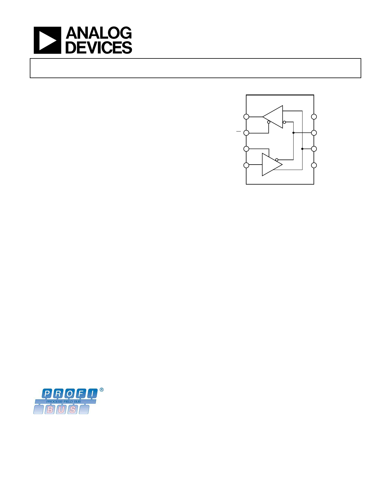
FUNCTIONAL BLOCK DIAGRAM
ADM1486
RO 1
R
8 VCC
RE 2
7B
DE 3
6A
DI 4
D
5 GND
Figure 1.
To ensure this, the ADM1486 driver features high output
impedance when disabled and when powered down. This
minimizes the loading effect when the transceiver is not being
used. The high impedance driver output is maintained over the
entire common-mode voltage range from −7 V to +12 V.
The receiver contains a fail-safe feature that results in a logic
high output state if the inputs are unconnected (floating).
The ADM1486 is fabricated on BiCMOS, an advanced mixed
technology process combining low power CMOS with fast
switching bipolar technology. All inputs and outputs contain
protection against ESD; all driver outputs feature high source
and sink current capability. An epitaxial layer is used to guard
against latch-up.
The ADM1486 features extremely fast and closely matched
switching, enable, and disable times. Minimal driver propaga-
tion delays permit transmission at data rates up to 30 Mbps
while low skew minimizes EMI interference.
The part is fully specified over the commercial and industrial
temperature range and is available in an 8-lead SOIC package.
Rev. A
Information furnished by Analog Devices is believed to be accurate and reliable.
However, no responsibility is assumed by Analog Devices for its use, nor for any
infringements of patents or other rights of third parties that may result from its use.
Specifications subject to change without notice. No license is granted by implication
or otherwise under any patent or patent rights of Analog Devices. Trademarks and
registered trademarks are the property of their respective owners.
One Technology Way, P.O. Box 9106, Norwood, MA 02062-9106, U.S.A.
Tel: 781.329.4700
www.analog.com
Fax: 781.461.3113 © 2005 Analog Devices, Inc. All rights reserved.
1 page 
ABSOLUTE MAXIMUM RATINGS
TA = 25°C, unless otherwise noted.
Table 3.
Parameter
VCC
Inputs
Driver Input (DI)
Control Inputs (DE, RE)
Receiver Inputs (A, B)
Outputs
Driver Outputs
Receiver Outputs
Power Dissipation 8-Lead SOIC
θJA, Thermal Impedance
Operating Temperature Range
Industrial (A Version)
Storage Temperature Range
Lead Temperature (Soldering, 10 sec)
Vapor Phase (60 sec)
Infrared (15 sec)
Rating
7V
−0.3 V to VCC + 0.3 V
−0.3 V to VCC + 0.3 V
−9 V to +14 V
−9 V to +14 V
−0.5 V to VCC + 0.5 V
450 mW
170°C/W
−40°C to +85°C
−65°C to +150°C
300°C
215°C
220°C
ADM1486
Stresses above those listed under Absolute Maximum Ratings
may cause permanent damage to the device. This is a stress
rating only; functional operation of the device at these or any
other conditions above those indicated in the in the operational
section of this specification is not implied. Exposure to absolute
maximum rating conditions for extended periods of time may
affect device reliability.
ESD CAUTION
ESD (electrostatic discharge) sensitive device. Electrostatic charges as high as 4000 V readily accumulate on
the human body and test equipment and can discharge without detection. Although this product features
proprietary ESD protection circuitry, permanent damage may occur on devices subjected to high energy
electrostatic discharges. Therefore, proper ESD precautions are recommended to avoid performance
degradation or loss of functionality.
Rev. A | Page 5 of 16
5 Page 
A
B
1, 2
CH1 1.00VΩ CH2 1.00VΩ M4.00ns CH1
1.72V
Figure 25. Unloaded Driver Differential Outputs
A
ADM1486
3 DI
A
B
1, 2
4
CH1 1.00VΩ
CH3 2.00VΩ
CH2 1.00VΩ M10.0ns CH1
CH4 5.00VΩ
RO
1.72V
Figure 28. Driver/Receiver Propagation Delays High to Low
(RLDiff = 54 Ω, CL1 = CL2 = 100 pF)
A
B
1, 2
CH1 500mVΩ CH2 500mVΩ M4.00ns CH1
1.72V
Figure 26. Loaded Driver Differential Output
(RLDiff = 54 Ω, CL1 = CL2 = 100 pF)
DI
3
A
B
1, 2
RO
4
CH1 1.00VΩ
CH3 2.00VΩ
CH2 1.00VΩ M10.0ns CH1
CH4 5.00VΩ
1.72V
Figure 27. Driver/Receiver Propagation Delays Low to High
(RLDIFF = 54 Ω, CL1 = CL2 = 100 pF)
B
1, 2
CH1 1.00VΩ CH2 1.00VΩ M10.0ns CH1
3.40V
Figure 29. Unloaded Driver Outputs at 15 Mbps
A
B
1, 2
CH1 1.00VΩ CH2 1.00VΩ M4.00ns CH1
3.40V
Figure 30. Unloaded Driver Outputs at 30 Mbps
Rev. A | Page 11 of 16
11 Page | ||
| Páginas | Total 16 Páginas | |
| PDF Descargar | [ Datasheet ADM1486.PDF ] | |
Hoja de datos destacado
| Número de pieza | Descripción | Fabricantes |
| ADM1485 | +-5 V Low Power EIA RS-485 Transceiver | Analog Devices |
| ADM1486 | 0.8 mA PROFIBUS RS-485 Transceiver | Analog Devices |
| ADM1487 | Ultralow Power RS-485/RS-422 Transceiver | Analog Devices |
| ADM1487E | (ADMx48xE) transceivers | Analog Devices |
| Número de pieza | Descripción | Fabricantes |
| SLA6805M | High Voltage 3 phase Motor Driver IC. |
Sanken |
| SDC1742 | 12- and 14-Bit Hybrid Synchro / Resolver-to-Digital Converters. |
Analog Devices |
|
DataSheet.es es una pagina web que funciona como un repositorio de manuales o hoja de datos de muchos de los productos más populares, |
| DataSheet.es | 2020 | Privacy Policy | Contacto | Buscar |