|
|
|
PDF ADS7830IPWT Data sheet ( Hoja de datos )
| Número de pieza | ADS7830IPWT | |
| Descripción | 8-Bit/ 8-Channel Sampling ANALOG-TO-DIGITAL CONVERTER with I2C Interface | |
| Fabricantes | Burr-Brown Corporation | |
| Logotipo | ||
Hay una vista previa y un enlace de descarga de ADS7830IPWT (archivo pdf) en la parte inferior de esta página. Total 16 Páginas | ||
|
No Preview Available !
ADS7830
ADS7830 ®
SBAS302 – DECEMBER 2003
8-Bit, 8-Channel Sampling
ANALOG-TO-DIGITAL CONVERTER
with I2C™ Interface
FEATURES
q 70kHz SAMPLING RATE
q ±0.5LSB INL/DNL
q 8 BITS NO MISSING CODES
q 4 DIFFERENTIAL/8 SINGLE-ENDED INPUTS
q 2.7V TO 5V OPERATION
q BUILT-IN 2.5V REFERENCE/BUFFER
q SUPPORTS ALL THREE I2C MODES:
Standard, Fast, and High-Speed
q LOW POWER:
180µW (Standard Mode)
300µW (High-Speed Mode)
675µW (Fast Mode)
q DIRECT PIN COMPATIBLE WITH ADS7828
q TSSOP-16 PACKAGE
APPLICATIONS
q VOLTAGE-SUPPLY MONITORING
q ISOLATED DATA ACQUISITION
q TRANSDUCER INTERFACE
q BATTERY-OPERATED SYSTEMS
q REMOTE DATA ACQUISITION
DESCRIPTION
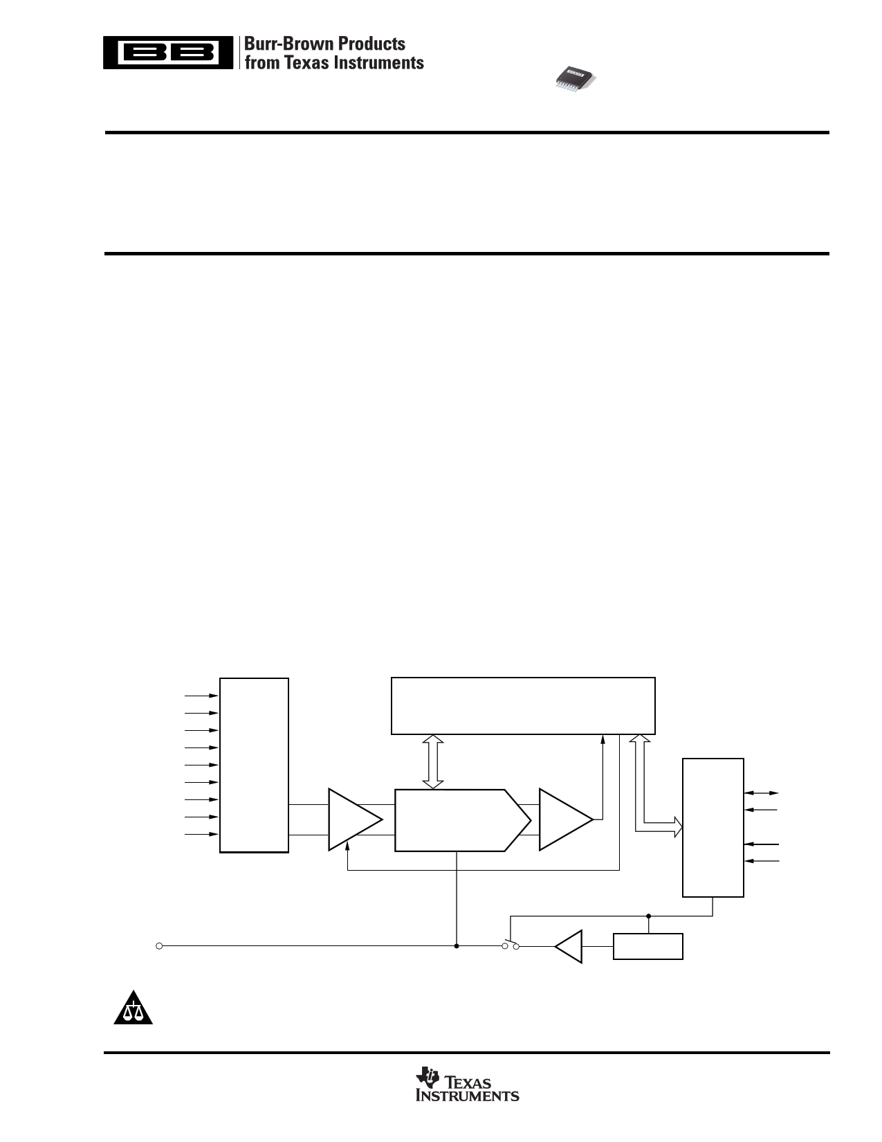
The ADS7830 is a single-supply, low-power, 8-bit data
acquisition device that features a serial I2C interface and an
8-channel multiplexer. The Analog-to-Digital (A/D) converter
features a sample-and-hold amplifier and internal,
asynchronous clock. The combination of an I2C serial,
2-wire interface and micropower consumption makes the
ADS7830 ideal for applications requiring the A/D converter to
be close to the input source in remote locations and for
applications requiring isolation. The ADS7830 is available in
a TSSOP-16 package.
CH0
CH1
CH2
CH3
CH4
CH5
CH6
CH7
COM
8-Channel
MUX
S/H Amp
SAR
CDAC
Comparator
Serial
Interface
SDA
SCL
A0
A1
REFIN/REFOUT
Buffer
2.5V VREF
Please be aware that an important notice concerning availability, standard warranty, and use in critical applications of
Texas Instruments semiconductor products and disclaimers thereto appears at the end of this data sheet.
All trademarks are the property of their respective owners.
PRODUCTION DATA information is current as of publication date.
Products conform to specifications per the terms of Texas Instruments
standard warranty. Production processing does not necessarily include
testing of all parameters.
www.ti.com
Copyright © 2003, Texas Instruments Incorporated
1 page 
TIMING DIAGRAM
SDA
SCL
tBUF
tLOW
tR
tF
tHD; STA
tHD; STA
STOP START
tHD; DAT
tHIGH tSU; DAT
tSU; STA
REPEATED
START
tSP
tSU; STO
TIMING CHARACTERISTICS(1)
At TA = –40°C to +85°C, +VDD = +2.7V, unless otherwise noted.
PARAMETER
SYMBOL
CONDITIONS
SCL Clock Frequency
fSCL
Bus Free Time Between a STOP and
START Condition
Hold Time (Repeated) START
Condition
LOW Period of the SCL Clock
tBUF
tHD;STA
tLOW
HIGH Period of the SCL Clock
tHIGH
Setup Time for a Repeated START
Condition
Data Setup Time
Data Hold Time
tSU;STA
tSU;DAT
tHD;DAT
Rise Time of SCL Signal
tRCL
Rise Time of SCL Signal After a
Repeated START Condition and
After an Acknowledge Bit
Fall Time of SCL Signal
tRCL1
tFCL
Standard Mode
Fast Mode
High-Speed Mode, CB = 100pF max
High-Speed Mode, CB = 400pF max
Standard Mode
Fast Mode
Standard Mode
Fast Mode
High-Speed Mode
Standard Mode
Fast Mode
High-Speed Mode, CB = 100pF max(2)
High-Speed Mode, CB = 400pF max(2)
Standard Mode
Fast Mode
High-Speed Mode, CB = 100pF max(2)
High-Speed Mode, CB = 400pF max(2)
Standard Mode
Fast Mode
High-Speed Mode
Standard Mode
Fast Mode
High-Speed Mode
Standard Mode
Fast Mode
High-Speed Mode, CB = 100pF max(2)
High-Speed Mode, CB = 400pF max(2)
Standard Mode
Fast Mode
High-Speed Mode, CB = 100pF max(2)
High-Speed Mode, CB = 400pF max(2)
Standard Mode
Fast Mode
High-Speed Mode, CB = 100pF max(2)
High-Speed Mode, CB = 400pF max(2)
Standard Mode
Fast Mode
High-Speed Mode, CB = 100pF max(2)
High-Speed Mode, CB = 400pF max(2)
MIN
4.7
1.3
4.0
600
160
4.7
1.3
160
320
4.0
600
60
120
4.7
600
160
250
100
10
0
0
0(3)
0(3)
20 + 0.1CB
10
20
20 + 0.1CB
10
20
20 + 0.1CB
10
20
MAX
100
400
3.4
1.7
3.45
0.9
70
150
1000
300
40
80
1000
300
80
160
300
300
40
80
UNITS
kHz
kHz
MHz
MHz
µs
µs
µs
ns
ns
µs
µs
ns
ns
µs
ns
ns
ns
µs
ns
ns
ns
ns
ns
µs
µs
ns
ns
ns
ns
ns
ns
ns
ns
ns
ns
ns
ns
ns
ns
ADS7830
SBAS302
www.ti.com
5
5 Page 
Address Byte
MSB
6
5
4
3
2
1 LSB
1 0 0 1 0 A1 A0 R/W
Command Byte
MSB
6
5
4
3
2
1 LSB
SD C2 C1 C0 PD1 PD0 X
X
The address byte is the first byte received following the
START condition from the master device. The first five bits
(MSBs) of the slave address are factory pre-set to 10010.
The next two bits of the address byte are the device select
bits, A1 and A0. Input pins (A1-A0) on the ADS7830 deter-
mine these two bits of the device address for a particular
ADS7830. A maximum of four devices with the same pre-set
code can therefore be connected on the same bus at one
time.
The A1-A0 Address Inputs can be connected to VDD or digital
ground. The device address is set by the state of these pins
upon power-up of the ADS7830.
The last bit of the address byte (R/W) defines the operation
to be performed. When set to a “1” a read operation is
selected; when set to a “0” a write operation is selected.
Following the START condition the ADS7830 monitors the
SDA bus, checking the device type identifier being transmit-
ted. Upon receiving the 10010 code, the appropriate device
select bits, and the R/W bit, the slave device outputs an
acknowledge signal on the SDA line.
The ADS7830’s operating mode is determined by a com-
mand byte which is illustrated above.
SD: Single-Ended/Differential Inputs
0: Differential Inputs
1: Single-Ended Inputs
C2 - C0: Channel Selections
PD1 - 0: Power-Down Selection
X: Unused
See Table I for Truth Table.
POWER-DOWN SELECTION
PD1
0
0
1
1
PD0
0
1
0
1
DESCRIPTION
Power Down Between A/D Converter Conversions
Internal Reference OFF and A/D Converter ON
Internal Reference ON and A/D Converter OFF
Internal Reference ON and A/D Converter ON
INITIATING CONVERSION
Provided the master has write-addressed it, the ADS7830
turns on the A/D converter’s section and begins conversions
when it receives BIT 4 of the command byte shown in the
Command Byte. If the command byte is correct, the ADS7830
will return an ACK condition.
CHANNEL SELECTION CONTROL
SD
C2
C1
C0
CH0
CH1
CH2
CH3
CH4
0
0
0
0
+IN –IN
—
—
—
0 0 0 1 — — +IN –IN —
0 0 1 0 — — — — +IN
0 0 1 1 —————
0
1
0
0
–IN +IN
—
—
—
0 1 0 1 — — –IN +IN —
0 1 1 0 — — — — –IN
0 1 1 1 —————
1 0 0 0 +IN — — — —
1 0 0 1 — — +IN — —
1 0 1 0 — — — — +IN
1 0 1 1 —————
1 1 0 0 — +IN — — —
1 1 0 1 — — — +IN —
1 1 1 0 —————
1 1 1 1 —————
TABLE I. Channel Selection Control Addressed by Command BYTE.
CH5
—
—
–IN
—
—
—
+IN
—
—
—
—
—
—
—
+IN
—
CH6
—
—
—
+IN
—
—
—
–IN
—
—
—
+IN
—
—
—
—
CH7
—
—
—
–IN
—
—
—
+IN
—
—
—
—
—
—
—
+IN
COM
—
—
—
—
—
—
—
—
–IN
–IN
–IN
–IN
–IN
–IN
–IN
–IN
ADS7830
SBAS302
www.ti.com
11
11 Page | ||
| Páginas | Total 16 Páginas | |
| PDF Descargar | [ Datasheet ADS7830IPWT.PDF ] | |
Hoja de datos destacado
| Número de pieza | Descripción | Fabricantes |
| ADS7830IPWR | 8-Bit/ 8-Channel Sampling ANALOG-TO-DIGITAL CONVERTER with I2C Interface | Burr-Brown Corporation |
| ADS7830IPWT | 8-Bit/ 8-Channel Sampling ANALOG-TO-DIGITAL CONVERTER with I2C Interface | Burr-Brown Corporation |
| Número de pieza | Descripción | Fabricantes |
| SLA6805M | High Voltage 3 phase Motor Driver IC. |
Sanken |
| SDC1742 | 12- and 14-Bit Hybrid Synchro / Resolver-to-Digital Converters. |
Analog Devices |
|
DataSheet.es es una pagina web que funciona como un repositorio de manuales o hoja de datos de muchos de los productos más populares, |
| DataSheet.es | 2020 | Privacy Policy | Contacto | Buscar |