|
|
|
PDF ADXL202E Data sheet ( Hoja de datos )
| Número de pieza | ADXL202E | |
| Descripción | Low-Cost +-2 g Dual-Axis Accelerometer with Duty Cycle Output | |
| Fabricantes | Analog Devices | |
| Logotipo | ||
Hay una vista previa y un enlace de descarga de ADXL202E (archivo pdf) en la parte inferior de esta página. Total 12 Páginas | ||
|
No Preview Available !
a Low-Cost ؎2 g Dual-Axis Accelerometer
with Duty Cycle Output
ADXL202E*
FEATURES
2-Axis Acceleration Sensor on a Single IC Chip
5 mm ؋ 5 mm ؋ 2 mm Ultrasmall Chip Scale Package
2 mg Resolution at 60 Hz
Low-Power < 0.6 mA
Direct Interface to Low-Cost Microcontrollers via
Duty Cycle Output
BW Adjustment with a Single Capacitor
3 V to 5.25 V Single Supply Operation
1000 g Shock Survival
APPLICATIONS
2-Axis Tilt Sensing with Faster Response than
Electrolytic, Mercury, or Thermal Sensors
Computer Peripherals
Information Appliances
Alarms and Motion Detectors
Disk Drives
Vehicle Security
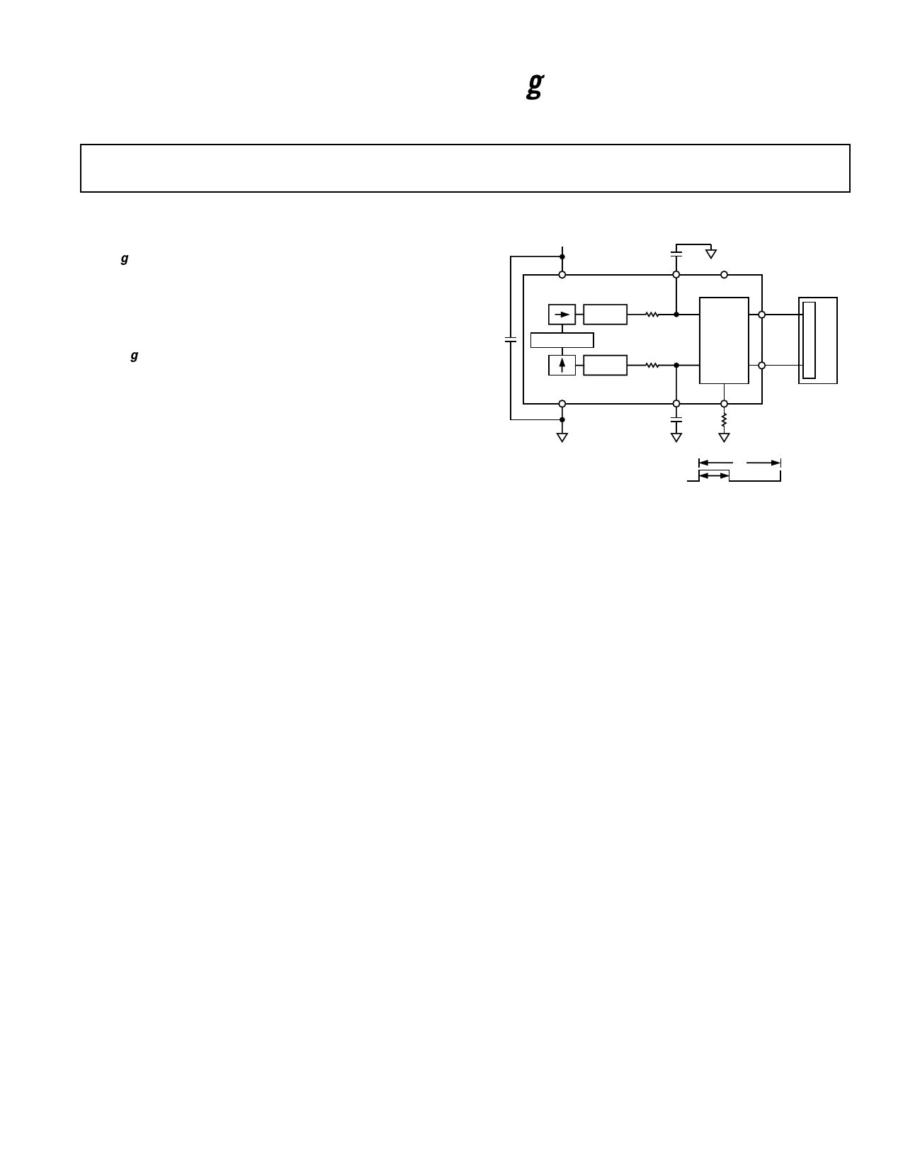
FUNCTIONAL BLOCK DIAGRAM
3V TO 5.25V
VDD
CX
XFILT
SELF-TEST
X SENSOR
DEMOD
RFILT
32k⍀
ANALOG
XOUT
C
O
CDC
OSCILLATOR
ADXL202E
TO
DUTY
U
N P
CYCLE
T
DEMOD
Y SENSOR
RFILT
32k⍀
(ADC)
YOUT
E
R
COM
YFILT
T2
CY RSET
T2
T1
A(g) = (T1/T2 – 0.5)/12.5%
0g = 50% DUTY CYCLE
T2 = RSET/125M⍀
GENERAL DESCRIPTION
The ADXL202E is a low-cost, low-power, complete 2-axis acceler-
ometer with a digital output, all on a single monolithic IC. It is an
improved version of the ADXL202AQC/JQC. The ADXL202E
will measure accelerations with a full-scale range of Ϯ2 g. The
ADXL202E can measure both dynamic acceleration (e.g., vibra-
tion) and static acceleration (e.g., gravity).
The outputs are analog voltage or digital signals whose duty cycles
(ratio of pulsewidth to period) are proportional to acceleration.
The duty cycle outputs can be directly measured by a micro-
processor counter, without an A/D converter or glue logic. The
duty cycle period is adjustable from 0.5 ms to 10 ms via a single
resistor (RSET).
The typical noise floor is 200 g√Hz, allowing signals below
2 mg (at 60 Hz bandwidth) to be resolved.
The bandwidth of the accelerometer is set with capacitors CX and
CY at the XFILT and YFILT pins. An analog output can be recon-
structed by filtering the duty cycle output.
The ADXL202E is available in 5 mm ϫ 5 mm ϫ 2 mm 8-lead
hermetic LCC package.
*Patents Pending
REV. A
Information furnished by Analog Devices is believed to be accurate and
reliable. However, no responsibility is assumed by Analog Devices for its
use, nor for any infringements of patents or other rights of third parties
which may result from its use. No license is granted by implication or
otherwise under any patent or patent rights of Analog Devices.
One Technology Way, P.O. Box 9106, Norwood, MA 02062-9106, U.S.A.
Tel: 781/329-4700 World Wide Web Site: http://www.analog.com
Fax: 781/326-8703
© Analog Devices, Inc., 2000
1 page 
VDD = 3 V
25
20
15
10
5
0
0.142
0.148
0.155
0.162 0.169
V/g
0.176
0.182
0.189
TPC 7. Y-Axis Sensitivity Distribution at YFILT, VDD = 3 V
30
25
20
15
10
5
0
9.50
9.90
10.4 10.8 11.3 11.8 12.2
PERCENT DUTY CYCLE/g
12.7
TPC 8. X-Axis Sensitivity at XOUT, VDD = 3 V
20
18
16
14
12
10
8
6
4
2
0
9.50
9.90
10.4 10.8 11.3 11.8 12.2
PERCENT DUTY CYCLE/g
12.7
TPC 9. Y-Axis Sensitivity at YOUT, VDD = 3 V
ADXL202E
VDD = 5 V
25
20
15
10
5
0
0.26 0.27 0.29 0.30 0.31 0.33 0.34 0.35
V/g
TPC 10. Y-Axis Sensitivity Distribution at YFILT, VDD = 5 V
25
20
15
10
5
0
10.3
10.8
11.3 11.8 12.3 12.8 13.3
PERCENT DUTY CYCLE/g
13.8
TPC 11. X-Axis Sensitivity at XOUT, VDD = 5 V
25
20
15
10
5
0
10.6
11.0
11.6 12.0 12.6 13.0 13.6
PERCENT DUTY CYCLE/g
14.0
TPC 12. Y-Axis Sensitivity at YOUT, VDD = 5 V
REV. A
–5–
5 Page 
ADXL202E
Table V. Trade-Offs Between Microcontroller Counter Rate,
T2 Period, and Resolution of Duty Cycle Modulator
Counter-
ADXL202E Clock Counts
RSET Sample
T2 (ms) (k⍀) Rate
Rate
per T2
(MHz) Cycle
Counts Resolution
per g (mg)
1.0 124 1000
1.0 124 1000
1.0 124 1000
5.0 625 200
5.0 625 200
5.0 625 200
10.0 1250 100
10.0 1250 100
10.0 1250 100
2.0 2000 250 4.0
1.0 1000 125 8.0
0.5 500 62.5 16.0
2.0 10000 1250 0.8
1.0 5000 625 1.6
0.5 2500 312.5 3.2
2.0 20000 2500 0.4
1.0 10000 1250 0.8
0.5 5000 625 1.6
STRATEGIES FOR USING THE DUTY CYCLE OUTPUT
WITH MICROCONTROLLERS
Application notes outlining various strategies for using the duty
cycle output with low cost microcontrollers are available from
the factory.
A DUAL AXIS TILT SENSOR: CONVERTING
ACCELERATION TO TILT
When the accelerometer is oriented so both its X and Y axes are
parallel to the earth’s surface it can be used as a two axis tilt sensor
with a roll and a pitch axis. Once the output signal from the
accelerometer has been converted to an acceleration that varies
between –1 g and +1 g, the output tilt in degrees is calculated as
follows:
Pitch = ASIN (Ax/1 g)
Roll = ASIN (Ay/1 g)
Be sure to account for overranges. It is possible for the acceler-
ometers to output a signal greater than ± 1 g due to vibration,
shock or other accelerations.
MEASURING 360؇ OF TILT
It is possible to measure a full 360° of orientation through gravity
by using two accelerometers oriented perpendicular to one another
(see Figure 5). When one sensor is reading a maximum change
in output per degree, the other is at its minimum.
X
USING THE ADXL202E AS A DUAL-AXIS TILT SENSOR
One of the most popular applications of the ADXL202E is tilt
measurement. An accelerometer uses the force of gravity as an
input vector to determine orientation of an object in space.
360؇ OF TILT
1g
An accelerometer is most sensitive to tilt when its sensitive axis
is perpendicular to the force of gravity, i.e., parallel to the earth’s
surface. At this orientation its sensitivity to changes in tilt is high-
est. When the accelerometer is oriented on axis to gravity, i.e.,
near its +1 g or –1 g reading, the change in output acceleration
per degree of tilt is negligible. When the accelerometer is perpen-
dicular to gravity, its output will change nearly 17.5 mg per degree
of tilt, but at 45° degrees it is changing only at 12.2 mg per
degree and resolution declines. The following table illustrates
the changes in the X and Y axes as the device is tilted ± 90°
through gravity.
X +90؇
0؇ 1g
X Axis
Orientation
to Horizon (؇)
–90
–75
–60
–45
–30
–15
0
15
30
45
60
75
90
Y
BOTTOM VIEW
–90؇
X Output
⌬ per
Degree of
X Output (g)
Tilt (mg)
–1.000
–0.966
–0.866
–0.707
–0.500
–0.259
0.000
0.259
0.500
0.707
0.866
0.966
1.000
–0.2
4.4
8.6
12.2
15.0
16.8
17.5
16.9
15.2
12.4
8.9
4.7
0.2
Y Output (g)
⌬ per
Degree of
Y Output (g)
Tilt (mg)
0.000
0.259
0.500
0.707
0.866
0.966
1.000
0.966
0.866
0.707
0.500
0.259
0.000
17.5
16.9
15.2
12.4
8.9
4.7
0.2
–4.4
–8.6
–12.2
–15.0
–16.8
–17.5
Figure 4. How the X and Y Axes Respond to Changes
in Tilt
Y
Figure 5. Using a Two-Axis Accelerometer to Measure
360° of Tilt
USING THE ANALOG OUTPUT
The ADXL202E was specifically designed for use with its digital
outputs, but has provisions to provide analog outputs as well.
Duty Cycle Filtering
An analog output can be reconstructed by filtering the duty cycle
output. This technique requires only passive components. The
duty cycle period (T2) should be set to <1 ms. An RC filter with a
3 dB point at least a factor of >10 less than the duty cycle fre-
quency is connected to the duty cycle output. The filter resistor
should be no less than 100 kΩ to prevent loading of the output
stage. The analog output signal will be ratiometric to the supply
voltage. The advantage of this method is an output scale factor of
approximately double the analog output. Its disadvantage is that
the frequency response will be lower than when using the XFILT,
YFILT output.
XFILT, YFILT Output
The second method is to use the analog output present at the
XFILT and YFILT pin. Unfortunately, these pins have a 32 kΩ
output impedance and are not designed to drive a load directly.
An op amp follower may be required to buffer this pin. The
advantage of this method is that the full 5 kHz bandwidth of the
accelerometer is available to the user. A capacitor still must be
added at this point for filtering. The duty cycle converter should
be kept running by using RSET <10 MΩ. Note that the acceler-
ometer offset and sensitivity are ratiometric to the supply voltage.
The offset and sensitivity are nominally:
0 g Offset = VDD/2
ADXL202E Sensitivity = (60 mV × VS)/g
REV. A
–11–
11 Page | ||
| Páginas | Total 12 Páginas | |
| PDF Descargar | [ Datasheet ADXL202E.PDF ] | |
Hoja de datos destacado
| Número de pieza | Descripción | Fabricantes |
| ADXL202 | Low Cost +-2 g/+-10 g Dual Axis iMEMS Accelerometers with Digital Output | Analog Devices |
| ADXL202E | Low-Cost +-2 g Dual-Axis Accelerometer with Duty Cycle Output | Analog Devices |
| Número de pieza | Descripción | Fabricantes |
| SLA6805M | High Voltage 3 phase Motor Driver IC. |
Sanken |
| SDC1742 | 12- and 14-Bit Hybrid Synchro / Resolver-to-Digital Converters. |
Analog Devices |
|
DataSheet.es es una pagina web que funciona como un repositorio de manuales o hoja de datos de muchos de los productos más populares, |
| DataSheet.es | 2020 | Privacy Policy | Contacto | Buscar |