|
|
|
PDF CAT5112 Data sheet ( Hoja de datos )
| Número de pieza | CAT5112 | |
| Descripción | 32-Tap Digitally Programmable Potentiometer (DPP) | |
| Fabricantes | Catalyst Semiconductor | |
| Logotipo | ||
Hay una vista previa y un enlace de descarga de CAT5112 (archivo pdf) en la parte inferior de esta página. Total 6 Páginas | ||
|
No Preview Available !
Advance Information
CAT5112
32-Tap Digitally Programmable Potentiometer (DPP™)
FEATURES
s 32 Position Linear Taper Potentiometer
s Non-volatile NVRAM Wiper Storage
s Low Power CMOS Technology
s Single Supply Operation: 2.5V-6.0V
s Increment Up/Down Serial Interface
s Resistance Values: 10K, 20K, 50K and 100K Ω
s Available in PDIP, SOIC, TSSOP and MSOP packages
APPLICATIONS
s Automated Product Calibration
s Remote Control Adjustments
s Offset, Gain and Zero Control Systems
s Tamper-Proof Calibrations
s Contrast, Brightness and Volume Controls
s Motor Controls and Feedback Systems
s Programmable Analog Functions
DESCRIPTION
The CAT5112 is a single digitally programmable
potentiometer (DPP™) designed as a electronic
replacement for mechanical potentiometers and trim
pots. Ideal for automated adjustments on high volume
production lines, they are also well suited for
applications where equipment requiring periodic
adjustment is either difficult to access or located in a
hazardous or remote environment.
The CAT5112 contains a 32-tap series resistor array
connected between two terminals RH and RL. An up/
down counter and decoder that are controlled by three
input pins, determines which tap is connected to the
wiper, RW. The CAT5112 wiper is buffered by an OP
AMP that operates rail to rail. The wiper setting, stored
in non-volatile NVRAM memory, is not lost when the
device is powered down and is automatically recalled
when power is returned. The wiper can be adjusted to
test new system values without effecting the stored
setting. Wiper-control of the CAT5112 is
accomplished with three input control pins, CS, U/D,
and INC. The INC input increments the wiper in the
direction which is determined by the logic state of
the U/D input. The CS input is used to select the
device and also store the wiper position prior to
power down.
The digitally programmable potentiometer can be
used as a three-terminal resistive divider or as a
two-terminal variable resistor. DPPs bring variability and
programmability to a wide variety of applications
including control, parameter adjustments, and
signal processing.
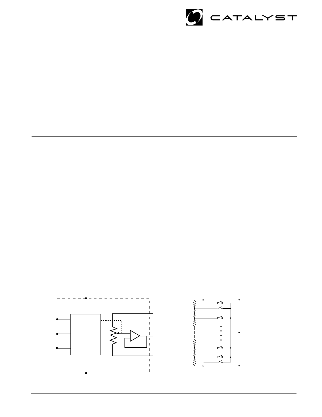
FUNCTIONAL DIAGRAM
VCC
U/D
Control
INC and
Memory
CS
VSS
© 2001 by Catalyst Semiconductor, Inc.
Characteristics subject to change without notice
RH
+
– R WB
RL
1
VH /RH
VW /RW
VL / R L
Implementation of the
Electronic Potentiometer
Doc. No. 25091-00 Rev. 3/28/01
M-1
1 page 
Advance Information
AC CONDITIONS OF TEST
VCC Range
Input Pulse Levels
Input Rise and Fall Times
Input Reference Levels
2.5V ≤ VCC ≤ 6V
0.2VCC to 0.7VCC
10ns
0.5VCC
AC OPERATING CHARACTERISTICS:
VCC = +2.5V to +6.0V, VH = VCC, VL = 0V, unless otherwise specified
Symbol Parameter
Min
tCI
tDI
tID
tIL
tIH
tIC
tCPH
tCPH
tIW
tCYC
tR, tF(2)
tPU(2)
tR VCC(2)
tWR
CS to INC Setup
U/D to INC Setup
U/D to INC Hold
INC LOW Period
INC HIGH Period
INC Inactive to CS Inactive
CS Deselect Time (NO STORE)
CS Deselect Time (STORE)
INC to VOUT Change
INC Cycle Time
INC Input Rise and Fall Time
Power-up to Wiper Stable
VCC Power-up Rate
Store Cycle
100
50
100
250
250
1
100
10
—
1
—
—
0.2
—
A. C. TIMING
Limits
Typ(1)
—
—
—
—
—
—
—
—
1
—
—
—
—
5
CAT5112
Max
—
—
—
—
—
—
—
—
5
—
500
1 msec
50
10
Units
ns
ns
ns
ns
ns
µs
ns
ms
µs
µs
µs
msec
V/ms
ms
CS
tCI
INC
U/D
tCYC
tIL tIH
tDI tID
tIW
W
tIC
(store)
tCPH
90%
90%
10%
tF tR
MI (3)
(1) Typical values are for TA=25oC and nominal supply voltage.
(2) This parameter is periodically sampled and not 100% tested.
(3) MI in the A.C. Timing diagram refers to the minimum incremental change in the W output due to a change in the wiper position.
5
Doc. No. 25091-00 Rev. 3/01
M-1
5 Page | ||
| Páginas | Total 6 Páginas | |
| PDF Descargar | [ Datasheet CAT5112.PDF ] | |
Hoja de datos destacado
| Número de pieza | Descripción | Fabricantes |
| CAT511 | 8-Bit Digital POT with Independent Reference Inputs | Catalyst Semiconductor |
| CAT5110 | 32-tap Digital Potentiometers | ON Semiconductor |
| CAT5110 | (CAT5110 - CAT5125) Digitally Programmable Potentiometers | Catalyst Semiconductor |
| CAT5111 | 100-Tap Digitally Programmable Potentiometer | ON Semiconductor |
| Número de pieza | Descripción | Fabricantes |
| SLA6805M | High Voltage 3 phase Motor Driver IC. |
Sanken |
| SDC1742 | 12- and 14-Bit Hybrid Synchro / Resolver-to-Digital Converters. |
Analog Devices |
|
DataSheet.es es una pagina web que funciona como un repositorio de manuales o hoja de datos de muchos de los productos más populares, |
| DataSheet.es | 2020 | Privacy Policy | Contacto | Buscar |