|
|
|
PDF FH26W-51S-0.3SHW Data sheet ( Hoja de datos )
| Número de pieza | FH26W-51S-0.3SHW | |
| Descripción | FPC Connector | |
| Fabricantes | Hirose Electric | |
| Logotipo | ||
Hay una vista previa y un enlace de descarga de FH26W-51S-0.3SHW (archivo pdf) en la parte inferior de esta página. Total 12 Páginas | ||
|
No Preview Available !
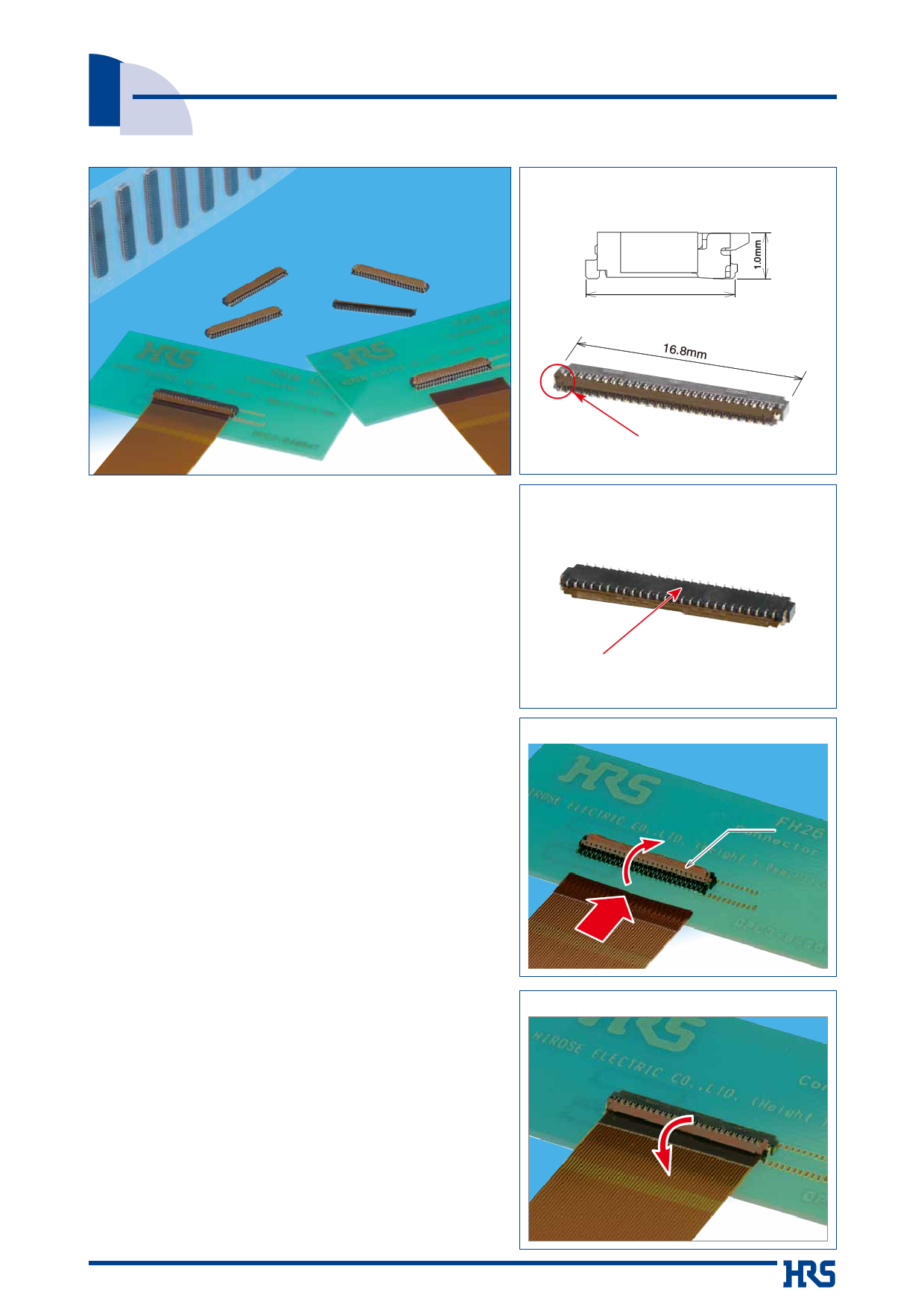
0.3 mm Pitch, 1.0 mm Height FPC Connector
FH26 Series
●Space saving(51 pos. shown)
3.2mm
16.8mm
Metal fittings do no protrude
outside of the connector body
■Features
1. Low-profile 0.3 mm pitch FPC connector
Ultra-thin design, 1.0 mm height, 3.2 mm width all add up
to a compact, space saving form factor.
*30% reduction in PCB footprint
*40% reduction in weight
(Compared to our 0.3 mm pitch FH23 Series 51 position connector.)
2. Easy PCB Mounting
The leads are double sided and have a 0.6 mm mounting
lead pitch to simplify mounting.
3. Fully molded structure aids PCB layout
The bottom of this connector is enclosed by a fully molded
structure that protects the contacts and removes any
restrictions from PCB patterning and design.
4. Rotating one-touch ZIF mechanism
The one-touch rotating ZIF mechanism is easier to operate and
works with a light force, and a clear tactile click is delivered upon
the successful completion of the mating process
5. Easy FPC insertion
The metal FPC insertion guides helps to make this the
FPC insertion process easier.
6. FPC. Accepts standard 0.2 mm thick FPC
This connector accepts standard 0.2 mm thick FPC. (The
proper FPC stiffener thickness will prevent FPC
deformation and ease insertion and mating.)
7. Supports automatic pick-n-place mounting
Offered in tape and reel packaging that is compatible with
automatic machine mounting. (5,000 pieces per reel)
8. Halogen-free
If you need a Halogen free connector, please use the
FH26W type. All materials and substances used to produce
the FH26W Series product complies with Halogen-free
standards. * Defined according to IEC61249-2-21
Br: 900ppm max, Cl: 900ppm max, Br+Cl: 1,500ppm max.
9. Multiple packing options
The standard packaging is 5,000 pieces per reel, but it is
also offered in a 500 piece reel. (The outer diameter of the
reel will be Ø180 mm in this case.)
●Can be mounted over conductive traces.
No exposed contacts on the bottom
of the connector
●Operation
((11)) AAccttuuaattoorr ooppeenn
((22)) IInnsseerrtt FFPPCC
Actuator
q
w
FPC
((33)) CClloossee tthhee aaccttuuaattoorr
((44)) FFPPCC ccoonnnneecctteedd
e
r
2013.11w
1
1 page 
FH26 Series●0.3mm Contact Pitch, 1mm above the board, Flexible Printed Circuit ZIF Connectors
■Recommended FPC Construction
●Contact FPC manufacturer for specific details.
1. Using Single-sided FPC
Connecting side
Material Name
Material
Thickness (μm)
Covering film layer.
Polyimide 1 mil thick.
25
Cover adhesive
Surface treatment
1μm to 5μm Nickel underplated
0.2μm Gold plated
25
3
Copper foil
Cu 1oz
35
Base adhesive
Thermosetting adhesive
25
Base film
Polyimide 1 mil thick
25
Reinforcement material adhesive Thermosetting adhesive
40
Stiffener
Polyimide 3 mil thick
75
Total
203
Back side
2. Using Double-sided FPC
Connecting side
Back side
Material Name
Material
Thickness (μm)
Covering layer film
Polyimide 1 mil thick
25
Cover adhesive
Surface treatment
1μm to 5μm Nickel underplated
0.2μm Gold plated
25
3
Through-hole copper
Cu
15
Copper foil
Cu 1/2oz
18
Base adhesive
Thermosetting adhesive
18
Base film
Polyimide 1 mil thick
25
Base adhesive
Thermosetting adhesive
18
Copper foil
Cu 1/2oz
18
Cover adhesive
Thermosetting adhesive
25
Covering layer film
Polyimide 1 mil thick
25
Reinforcement material adhesive Thermosetting adhesive
25
Stiffener
Polyimide 1 mil thick
25
Total
197
●To prevent release of the FPC due to it's bending, use of double sided FPC with copper foil on the back side is NOT RECOMMENDED.
3. Precautions
1. This specification is a recommendation for the construction of the FH26 Series FPC (t=0.2 ± 0.03).
2. For details about the construction, please contact the FPC manufacturers.
5
5 Page 
FH26 Series●0.3mm Contact Pitch, 1mm above the board, Flexible Printed Circuit ZIF Connectors
Precautions
SFPC Insertionw
Do not insert the FPC at any angle from above.
As illustrated, angle insertion may cause electrical discontinuity when the FPC is deflected in use.
*To avert insertion of the FPC on an angle, consideration should be given to securing FPC insertion
space at the time of board layout. Insertion will be difficult when the FPC is too short.
*Contact the FPC manufacturer for information about the bending specifications.
SVerification of the fully closed actuator.
The actuator should be fully closed (as illustrated) and the FPC held firmly in the connector.
Do not press against the actuator when is fully closed. Max force applied to the fully closed actuator
should not exceed 1 N.
Routing the FPC (FPC fully inserted/ actuator closed)
SFPC Load
Do not apply force in excess of 0.05N/pin max. in the upward direction (as illustrated). Do not bend
the FPC too close to the actuator.
Load: 0.05N/pin max.
11
11 Page | ||
| Páginas | Total 12 Páginas | |
| PDF Descargar | [ Datasheet FH26W-51S-0.3SHW.PDF ] | |
Hoja de datos destacado
| Número de pieza | Descripción | Fabricantes |
| FH26W-51S-0.3SHW | FPC Connector | Hirose Electric |
| Número de pieza | Descripción | Fabricantes |
| SLA6805M | High Voltage 3 phase Motor Driver IC. |
Sanken |
| SDC1742 | 12- and 14-Bit Hybrid Synchro / Resolver-to-Digital Converters. |
Analog Devices |
|
DataSheet.es es una pagina web que funciona como un repositorio de manuales o hoja de datos de muchos de los productos más populares, |
| DataSheet.es | 2020 | Privacy Policy | Contacto | Buscar |