|
|
|
PDF FBM85N80B Data sheet ( Hoja de datos )
| Número de pieza | FBM85N80B | |
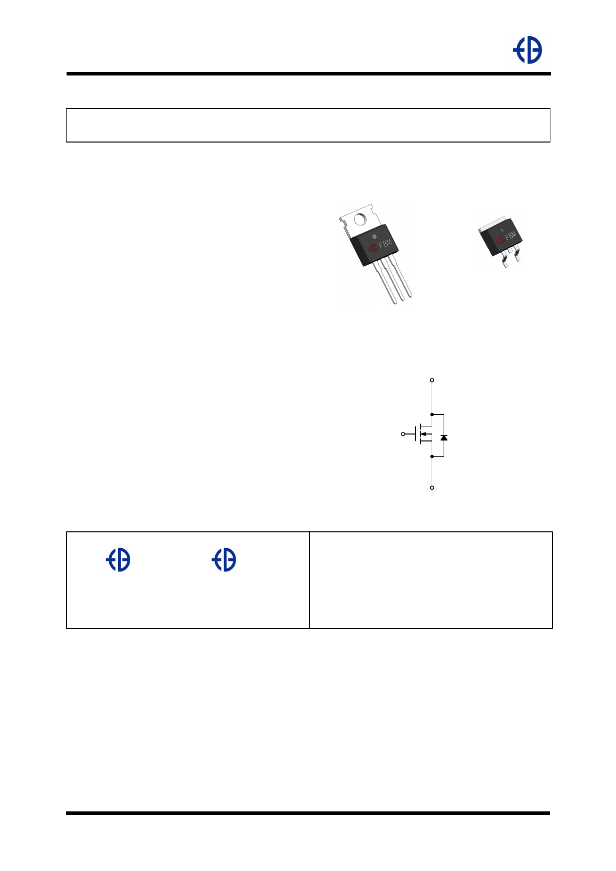
| Descripción | N-Channel Enhancement Mode MOSFET | |
| Fabricantes | FBM | |
| Logotipo | ||
Hay una vista previa y un enlace de descarga de FBM85N80B (archivo pdf) en la parte inferior de esta página. Total 11 Páginas | ||
|
No Preview Available !
FBM85N80P/B
FBM@
N-Channel Enhancement Mode MOSFET
Features
• 80V/90A
RDS(ON) = 7.0 mΩ (typ.) @ VGS=10V
• 100% avalanche tested
• Reliable and Rugged
• Lead Free and Green Devices Available
(RoHS Compliant)
Applications
• Switching application
• Power Management for Inverter Systems.
Pin Description
DS
G
TO-220FB-3L
D
DS
G
TO-263-2L
G N-Channel MOSFET
Ordering and Marking Information
S
P
FBM85N80
YYÿ XXXJWW G
B
FBM85N80
YYÿ XXXJWW G
Package Code
P : TO-220FB-3L B : TO-263-2L
Date Code
YYXXX WW
Assembly Material
G : Lead Free Device
Note: FBM lead-free products contain molding compounds/die attach materials and 100% matte tin plate termin-
ation finish; which are fully compliant with RoHS. FBM lead-free products meet or exceed the lead-free requirements
of IPC/JEDEC J-STD-020C for MSL classification at lead-free peak reflow temperature. FBM defines “Green” to mean
lead-free (RoHS compliant) and halogen free (Br or Cl does not exceed 900ppm by weight in homogeneous material
and total of Br and Cl does not exceed 1500ppm by weight).
FBM reserves the right to make changes to improve reliability or manufacturability without notice, and advise
customers to ob tain th e l atest version of rel evant inf ormation to verif y b ef ore pl acing ord ers.
1 150623
1 page 
FBM85N80P/B
FBM@
Typical Operating Characteristics (Cont.)
Output Characteristics
160
V = 7,8,9,10V
GS
140
6V
120
100
5.5V
80
60 5V
40
4.5V
20
0
01 2 3 4 5 6
VDS - Drain-Source Voltage (V)
Drain-Source On Resistance
10
9.0
8.0 VGS =10V
7.0
6.0
0
20 40 60 80 100
ID - Drain Current (A)
Drain-Source On Resistance
17
I =45A
DS
15
13
11
9
7
5
4 5 6 7 8 9 10
VGS - Gate - Source Voltage (V)
Gate Threshold Voltage
1.6
I
DS
=250µA
1.4
1.2
1.0
0.8
0.6
0.4
0.2
-50 -25 0 25 50 75 100 125 150 175
Tj - Junction Temperature (°C)
5
5 Page 
FBM85N80P/B
FBM@
Classification Reflow Profiles
Profile Feature
Sn-Pb Eutectic Assembly
Pb-Free Assembly
Preheat & Soak
Temperature min (Tsmin)
Temperature max (Tsmax)
Time (Tsmin to Tsmax) (ts)
100 °C
150 °C
60-120 seconds
150 °C
200 °C
60-120 seconds
Average ramp-up rate
(Tsmax to TP)
Liquidous temperature (TL)
Time at liquidous (tL)
Peak package body Temperature
(Tp)*
Time (tP)** within 5°C of the specified
classification temperature (Tc)
Average ramp-down rate (Tp to Tsmax)
3 °C/second max.
183 °C
60-150 seconds
See Classification Temp in table 1
20** seconds
6 °C/second max.
3°C/second max.
217 °C
60-150 seconds
See Classification Temp in table 2
30** seconds
6 °C/second max.
Time 25°C to peak temperature
6 minutes max.
8 minutes max.
* Tolerance for peak profile Temperature (Tp) is defined as a supplier minimum and a user maximum.
** Tolerance for time at peak profile temperature (tp) is defined as a supplier minimum and a user maximum.
Table 1. SnPb Eutectic Process – Classification Temperatures (Tc)
Package
Volume mm3
Thickness
<350
<2.5 mm
235 °C
≥2.5 mm
220 °C
Volume mm3
≥350
220 °C
220 °C
Table 2. Pb-free Process – Classification Temperatures (Tc)
Package
Volume mm3
Thickness
<350
<1.6 mm
260 °C
1.6 mm – 2.5 mm
260 °C
≥2.5 mm
250 °C
Volume mm3
350-2000
260 °C
250 °C
245 °C
Volume mm3
>2000
260 °C
245 °C
245 °C
Reliability Test Program
Test item
SOLDERABILITY
HOLT
PCT
TCT
Method
JESD-22, B102
JESD-22, A108
JESD-22, A102
JESD-22, A104
Description
5 Sec, 245°C
1000 Hrs, Bias @ 125°C
168 Hrs, 100%RH, 2atm, 121°C
500 Cycles, -65°C~150°C
11
11 Page | ||
| Páginas | Total 11 Páginas | |
| PDF Descargar | [ Datasheet FBM85N80B.PDF ] | |
Hoja de datos destacado
| Número de pieza | Descripción | Fabricantes |
| FBM85N80B | N-Channel Enhancement Mode MOSFET | FBM |
| FBM85N80P | N-Channel Enhancement Mode MOSFET | FBM |
| Número de pieza | Descripción | Fabricantes |
| SLA6805M | High Voltage 3 phase Motor Driver IC. |
Sanken |
| SDC1742 | 12- and 14-Bit Hybrid Synchro / Resolver-to-Digital Converters. |
Analog Devices |
|
DataSheet.es es una pagina web que funciona como un repositorio de manuales o hoja de datos de muchos de los productos más populares, |
| DataSheet.es | 2020 | Privacy Policy | Contacto | Buscar |