|
|
|
PDF NJM2278 Data sheet ( Hoja de datos )
| Número de pieza | NJM2278 | |
| Descripción | 300/400MHz Band 20mW Power Amplifier | |
| Fabricantes | New Japan Radio | |
| Logotipo | ||
Hay una vista previa y un enlace de descarga de NJM2278 (archivo pdf) en la parte inferior de esta página. Total 13 Páginas | ||
|
No Preview Available !
NJM2278
300/400MHz Band 20mW Power Amplifier
GENERAL DESCRIPTION
PACKAGE OUTLINE
The NJM2278 is a narrow band, small signal amplifier, especially
designed for use as the final RF amplifier in 300MHz / 400MHz
band transmitter. The amplifier produces an output power of up to
20mW at the desired frequency, which frequency and power are
adjusted by external input and output matching circuits. It also
features excellent thermal stability of power gain.
NJM2278F1
APPLICATIONS
300/400MHz Band Applications, 400MHz Industrial Radios, Digital Communication Systems
FEATURES (@400MHz, 2.7V)
Low Operating Voltage
2V to 5.5V
Low Operating Current
20 mA @ 0dBm input
Power Gain
17dB @ - 30dBm input
13dB @0dBm input
Saturation Output
14dBm @3dBm input
Variable Power Gain Control 4dB
Excellent Power Gain Thermal Stability
Gain Flatness ±1dB (- 40°C to + 85°C)
RF IN Input Impedance
70 Ω
RF OUT Output Impedance 110 Ω
Recommended Operating Frequency 300MHz to 500MHz
Bipolar Technology
Package Outline
SOT-23-6-1
Note: For the signals at frequencies other than recommended operating frequency range of 300 to 500MHz,
please refer to the “TYPICAL CHARACTERISTICS”.
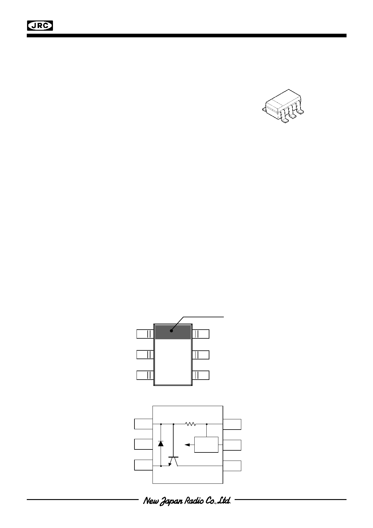
PIN CONFIGULATION
1
2
3
Orientation Mark
6
5
Top View
4
Pin Function
1. RF IN
2. GND
3. EMI
4. RF OUT
5. V+
6. IREF
Function Block Diagram
RF IN
1
GND
2
EM I
3
Regulator
Bias
IREF
6
V+
5
RF OUT
4
Ver.2016-08-22
-1-
1 page 
NJM2278
Test Circuit 5 for S-Parameters (this item is not specified in “ELECTRICAL CHARACTERISTICS”)
RF IN
Port1
Netw ork Analyzer
Z=50
Port2
RF IN
1
GND
2
EM I
3
Regulator
Bias
IREF C6
1000p
6
V+
5
RF OUT
4
V+
C7
1000p
RF OUT
Ver.2016-08-22
-5-
5 Page 
Input Return Loss S|11|2 versus
Frequency fin
Circuit 3, Pin= 0dBm
0
-5 85°C
-10 25°C
- 40°C
-15
-20
-25
-30
300 325 350 375 400 425 450 475 500
fin [MHz]
RF OUT - RF IN Isolation ISL versus
Frequency fin
0 Circuit 3, Pin= 0dBm
-5
-10
-15
-20
-25
85°C
25°C
- 40°C
-30
300 325 350 375 400 425 450 475 500
fin [MHz]
Output Power Pout versus
Input Power Pin
20 Circuit 1
- 40°C
15
10
85°C 25°C
5
0
-5
-10
-15
-20
-25
-40 -30 -20 -10
Pin [dBm]
0
10
Ver.2016-08-22
NJM2278
Output Return Loss S|22|2 versus
Frequency fin
0 Circuit 3, Pin= 0dBm
- 40°C
-5
85°C
25°C
-10
-15
-20
-25
-30
300 325 350 375 400 425 450 475 500
fin [MHz]
RF OUT - RF IN Isolation ISL versus
Ambient Temperature Ta
Circuit 3, Pin= 0dBm
0
-5
-10
-15
-20
-25
-30
-50 -25 0
25 50 75 100 125
Ta[°C]
Output Power Pout versus
Input Power Pin
20 Circuit 1
5.5V
15
10
2V 2.7V
5
0
-5
-10
-15
-20
-25
-40 -30 -20 -10 0 10
Pin [dBm]
- 11 -
11 Page | ||
| Páginas | Total 13 Páginas | |
| PDF Descargar | [ Datasheet NJM2278.PDF ] | |
Hoja de datos destacado
| Número de pieza | Descripción | Fabricantes |
| NJM2273 | 3-INPUT 1MUTE VIDEO SWITCH | New Japan Radio |
| NJM2274 | LOW POWER VIDEO AMPLIFIER WITH Y-C MIXER | New Japan Radio |
| NJM2274A | Low Power Video Amplifier | New Japan Radio |
| NJM2275 | RF Amplifier / SOT-23-6(MTP6) | JRC |
| Número de pieza | Descripción | Fabricantes |
| SLA6805M | High Voltage 3 phase Motor Driver IC. |
Sanken |
| SDC1742 | 12- and 14-Bit Hybrid Synchro / Resolver-to-Digital Converters. |
Analog Devices |
|
DataSheet.es es una pagina web que funciona como un repositorio de manuales o hoja de datos de muchos de los productos más populares, |
| DataSheet.es | 2020 | Privacy Policy | Contacto | Buscar |