|
|
|
PDF ADXL180 Data sheet ( Hoja de datos )
| Número de pieza | ADXL180 | |
| Descripción | iMEMS Accelerometer | |
| Fabricantes | Analog Devices | |
| Logotipo | ||
Hay una vista previa y un enlace de descarga de ADXL180 (archivo pdf) en la parte inferior de esta página. Total 30 Páginas | ||
|
No Preview Available !
FEATURES
Wide sensor range: 50 g to 500 g
Adjustable filter bandwidth: 100 Hz to 800 Hz
Configurable communication protocol
2-wire, current mode bus interface
Selectable sensor data resolution: 8 bit or 10 bit
Continuous auto-zero
Fully differential sensor and interface circuitry
High resistance to EMI/RFI
Sensor self-test
5.0 V to 14.5 V operation
8 bits of user-defined OTP memory
32-bit electronic serial number
Dual device per bus option
APPLICATIONS
Crash sensing
Configurable, High g,
iMEMS Accelerometer
ADXL180
GENERAL DESCRIPTION
The ADXL180 iMEMS® accelerometer is a configurable, single
axis, integrated satellite sensor that enables low cost solutions
for front and side impact airbag applications. Acceleration data
is sent to the control module via a digital 2-wire current loop
interface bus. The communication protocol is programmable for
compatibility with various automotive interface bus standards.
The sensor g range is configurable to provide full-scale ranges
from ±50 g to ±500 g. The sensor signal third-order, low-pass
Bessel filter bandwidth is configurable at 100 Hz, 200 Hz,
400 Hz, and 800 Hz.
The 10-bit analog-to-digital converter (ADC) allows either 8-bit
or 10-bit acceleration data to be transmitted to the control module.
Each part has a unique electronic serial number. The device is
rated for operation from −40°C to +125°C and is available in a
5 mm × 5 mm LFCSP package.
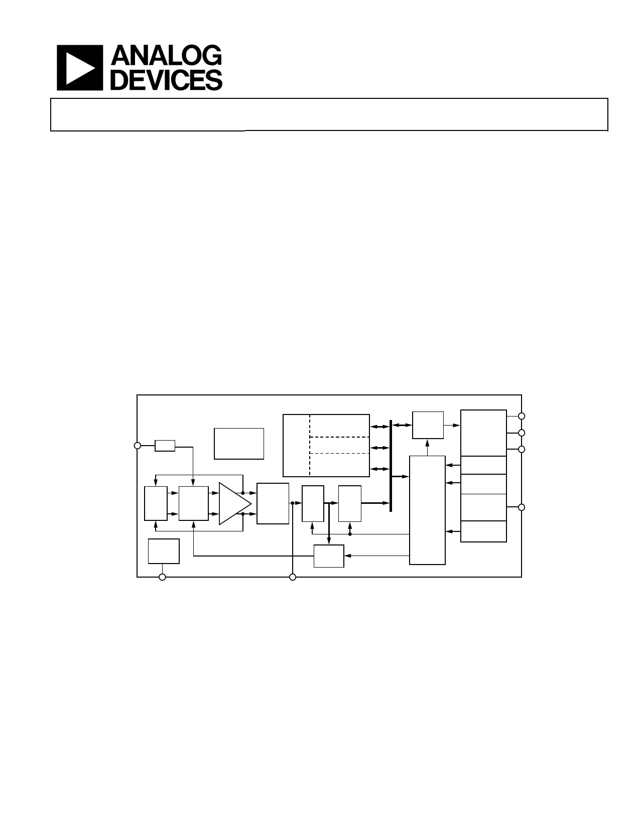
FUNCTIONAL BLOCK DIAGRAM
ADXL180
VSCI
V/Q
OSCILLATOR/
TIMING
GENERATOR
OTP
FUSE
ROM
SERIAL
NUMBER
TRIMS
CONFIGURATION
DATA
SERIAL
PORT
MOD
DIFF
SENSOR
DEMOD
AMP
3-POLE
BESSEL
FILTER
10-
BIT
ADC
AUTO-
ZERO
STATE
MACHINE
VCM
REF
VCM
SELF-
TEST
VSCO
Figure 1.
COMM
INTERFACE
SYNC
DETECT
PROGRAM
INTERFACE
VOLTAGE
REGULATOR
SUPPLY
MONITOR
VBP
VBC
VBN
VDD
Rev. A
Information furnished by Analog Devices is believed to be accurate and reliable. However, no
responsibility is assumed by Analog Devices for its use, nor for any infringements of patents or other
rights of third parties that may result from its use. Specifications subject to change without notice. No
license is granted by implication or otherwise under any patent or patent rights of Analog Devices.
Trademarksandregisteredtrademarksarethepropertyoftheirrespectiveowners.
One Technology Way, P.O. Box 9106, Norwood, MA 02062-9106, U.S.A.
Tel: 781.329.4700
www.analog.com
Fax: 781.461.3113
©2008 Analog Devices, Inc. All rights reserved.
1 page 
ADXL180
SPECIFICATIONS
TA = −40°C to +125°C, VBP − VBN = 5.0 V to 14.5 V, fLP = 400 Hz, acceleration = 0 g, unless otherwise noted.
Table 1.
Parameter1
SENSOR
Scale Factor
50 g Range
8-Bit Data
10-Bit Data
100 g Range
8-Bit Data
10-Bit Data
150 g Range
8-Bit Data
10-Bit Data
200 g Range
8-Bit Data
10-Bit Data
250 g Range
8-Bit Data
10-Bit Data
350 g Range
8-bit Data
10-bit Data
500 g Range
8-Bit Data
10-Bit Data
Offset
8-Bit Data
10-Bit Data
Noise (Peak-to-Peak)
8-Bit Data
10-Bit Data
Self Test
Amplitude
Internal Self-Test Limit
Nonlinearity
Cross-Axis Sensitivity
Resonant Frequency
Q
LOW-PASS FILTER
Frequency Response
Pass Band
−3 dB Frequency
−3 dB Frequency
−3 dB Frequency
−3 dB Frequency
AUTO-ZERO
Update Rate
Slow Mode
Fast Mode
Symbol Min Typ
Max Unit Test Conditions/Comments
0.465 0.50
0.116 0.1250
0.535 g/LSB
0.134 g/LSB
Measurement frequency: 100 Hz
See Table 37
0.930 1.00
0.233 0.2500
1.070 g/LSB
0.268 g/LSB
1.395 1.50
0.349 0.3750
1.605 g/LSB
0.401 g/LSB
1.860 2.00
0.465 0.5000
2.140 g/LSB
0.535 g/LSB
2.325 2.50
0.581 0.625
2.675 g/LSB
0.669 g/LSB
3.255 3.50
0.830 0.8925
3.745 g/LSB
0.955 g/LSB
4.650 5.00
1.163 1.2500
−12
−48
2
5.350 g/LSB
1.338 g/LSB
+11 LSB
+47 LSB
2 LSB
3 LSB
All ranges, auto-zero disabled
50 g range
10 Hz to 400 Hz
10 Hz to 400 Hz
20 25
20
0.2
−5
12.8
1.5
30 g
30 g
2%
+5 %
kHz
STI enabled, see Table 35
Of full-scale range
Third-order
Bessel
fLP Programmable, see Table 38
670 800
880 Hz
335 400
440 Hz
167.5 200
220 Hz
83.75 100
110 Hz
5.0 sec/LSB 10-bit LSB
0.5 sec/LSB 10-bit LSB
Rev. A | Page 4 of 60
5 Page 
ADXL180
THEORY OF OPERATION
OVERVIEW
The ADXL180 is a complete satellite system, including
acceleration sensor, data filtering, digital protocol functionality,
and a 2-wire, high-voltage, current-modulated bus interface
communications port.
ACCELERATION SENSOR
The ADXL180 provides a fully differential sensor structure and
circuit path. This device uses electrical feedback with zero force
feedback. Figure 4 is a simplified view of one of the differential
sensor elements. Each sensor includes several differential capa-
citor unit cells. Each cell is composed of fixed plates attached to the
substrate and movable plates attached to the frame. Displacement
of the frame changes the differential capacitance, which the on-
chip circuitry measures.
Complementary signals drive the fixed capacitor plates. The
relative phasing between the two halves of the differential
sensor is such that the displacement signal is differential
between the two measurement channels. Using the fully
differential sensor and an antiphase clocking scheme helps
reject electrical environmental noise (see Figure 5).
The ADXL180 acceleration sensor uses two electrically isolated,
mechanically coupled sensors to measure acceleration as shown
in Figure 5. The clock phasing of the readout is such that the
electrical signal due to acceleration is differential between the
channels and environmental disturbances couple in as a common-
mode signal. The following differential amplifier can then extract
the acceleration signal while suppressing the environmental noise.
Electrical feedback adjusts the amplitudes of the fixed capacitor
plates’ drive signals such that the ac signal on the moving plates
is zero. The feedback signal is linearly proportional to the applied
acceleration. This feedback technique ensures that there is no
net electrostatic force applied to the sensor.
PLATE
CAPACITORS
ANCHOR
MOVABLE
FRAME
UNIT SENSING
CELL
FIXED
PLATES
MOVING
PLATE
UNIT SELF-TEST
FORCING CELL
ANCHOR
Figure 4. Simplified View of ADXL180 Sensor Under Acceleration
ACCELERATION SENSING AXIS
+X-AXIS SENSOR
+
EMI DISTURBANCE RESPONSE
COMMON TO BOTH CHANNELS
SPRING
ISOLATED
MECHANICAL
COUPLINGS
–X-AXIS SENSOR
0
+
AMP
–
0
ACCELERATION RESPONSE
DIFFERENTIAL BETWEEN CHANNELS
–
Figure 5. Differential Acceleration Sensing
Rev. A | Page 10 of 60
VOUT
11 Page | ||
| Páginas | Total 30 Páginas | |
| PDF Descargar | [ Datasheet ADXL180.PDF ] | |
Hoja de datos destacado
| Número de pieza | Descripción | Fabricantes |
| ADXL180 | iMEMS Accelerometer | Analog Devices |
| ADXL185B | Single-Axis PSI5-Compatible Satellite Sensor | Analog Devices |
| ADXL189B | Single-Axis PSI5-Compatible Satellite Sensor | Analog Devices |
| Número de pieza | Descripción | Fabricantes |
| SLA6805M | High Voltage 3 phase Motor Driver IC. |
Sanken |
| SDC1742 | 12- and 14-Bit Hybrid Synchro / Resolver-to-Digital Converters. |
Analog Devices |
|
DataSheet.es es una pagina web que funciona como un repositorio de manuales o hoja de datos de muchos de los productos más populares, |
| DataSheet.es | 2020 | Privacy Policy | Contacto | Buscar |