|
|
|
PDF CAT24C02C Data sheet ( Hoja de datos )
| Número de pieza | CAT24C02C | |
| Descripción | 2K-Bit Serial E2PROM | |
| Fabricantes | Catalyst Semiconductor | |
| Logotipo | ||
Hay una vista previa y un enlace de descarga de CAT24C02C (archivo pdf) en la parte inferior de esta página. Total 9 Páginas | ||
|
No Preview Available !
CAT24C02C
2K-Bit Serial E2PROM
FEATURES
s 400 KHZ I2C Bus Compatible*
s 1.8 to 6.0Volt Operation
s Low Power CMOS Technology
DESCRIPTION
The CAT24C02C is a 2K-bit Serial CMOS E2PROM
internally organized as 256 words of 8 bits each. Catalyst’s
advanced CMOS technology substantially reduces de-
vice power requirements. The the CAT24C02C features
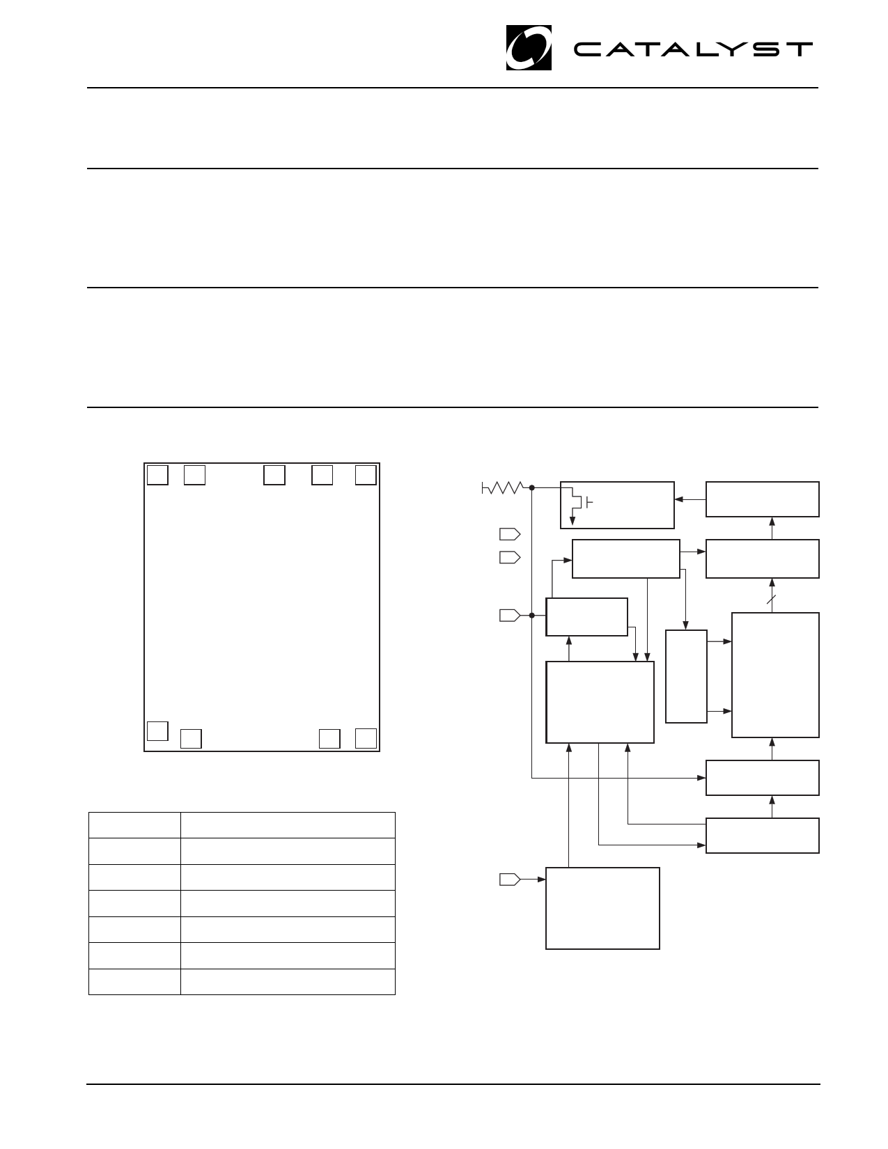
DIE PAD CONFIGURATION
VSS
DC
DC DC
VCC
s Page Write Buffer
s Self-Timed Write Cycle with Auto-Clear
s 1,000,000 Program/Erase Cycles
s 100 Year Data Retention
a 16-byte page write buffer. The device operates via the
I2C bus serial interface and has a ISO 7816 compatible
pinout.
BLOCK DIAGRAM
EXTERNAL LOAD
VCC
VSS
DOUT
ACK
WORD ADDRESS
BUFFERS
SENSE AMPS
SHIFT REGISTERS
COLUMN
DECODERS
SDA
START/STOP
LOGIC
SDA
NC
NC
SCL
PIN FUNCTIONS
Pin Name
Function
NC No Connect
SDA
Serial Data/Address
SCL Serial Clock
VCC +1.8V to +6.0V Power Supply
VSS Ground
DC Don't Connect
CONTROL
LOGIC
XDEC
E2PROM
DATA IN STORAGE
HIGH VOLTAGE/
TIMING CONTROL
SCL STATE COUNTERS
SLAVE
ADDRESS
COMPARATORS
* Catalyst Semiconductor is licensed by Philips Corporation to carry the I2C Bus Protocol.
© 1999 by Catalyst Semiconductor, Inc.
Characteristics subject to change without notice
1
Doc. No. 25086 -00 8/99 S-1
1 page 
CAT24C02C
START Condition
The START Condition precedes all commands to the
device, and is defined as a HIGH to LOW transition of
SDA when SCL is HIGH. The CAT24C02C monitor the
SDA and SCL lines and will not respond until this
condition is met.
STOP Condition
A LOW to HIGH transition of SDA when SCL is HIGH
determines the STOP condition. All operations must end
with a STOP condition.
DEVICE ADDRESSING
The bus Master begins a transmission by sending a
START condition. The Master then sends the address
of the particular slave device it is requesting. The four
most significant bits of the 8-bit slave address are fixed
as 1010 for the CAT24C02C (see Fig. 5). The next three
significant bits are all zeros. The last bit of the slave
address specifies whether a Read or Write operation is
to be performed. When this bit is set to 1, a Read
operation is selected, and when set to 0, a Write opera-
tion is selected.
After the Master sends a START condition and the slave
address byte, the CAT24C02C monitors the bus and
responds with an acknowledge (on the SDA line). The
CAT24C02C then performs a Read or Write operation
depending on the state of the R/W bit.
Acknowledge
After a successful data transfer, each receiving device is
required to generate an acknowledge. The acknowledg-
ing device pulls down the SDA line during the ninth clock
cycle, signaling that it received the 8 bits of data.
Figure 4. Acknowledge Timing
The CAT24C02C responds with an acknowledge after
receiving a START condition and its slave address. If the
device has been selected along with a write operation,
it responds with an acknowledge after receiving each 8-
bit byte.
When the CAT24C02C is in a READ mode it transmits
8 bits of data, releases the SDA line, and monitors the
line for an acknowledge. Once it receives this acknowl-
edge, the CAT24C02C will continue to transmit data. If
no acknowledge is sent by the Master, the device
terminates data transmission and waits for a STOP
condition.
WRITE OPERATIONS
Byte Write
In the Byte Write mode, the Master device sends the
START condition and the slave address information
(with the R/W bit set to zero) to the Slave device. After
the Slave generates an acknowledge, the Master sends
the byte address that is to be written into the address
pointer of the CAT24C02C. After receiving another
acknowledge from the Slave, the Master device trans-
mits the data byte to be written into the addressed
memory location. The CAT24C02C acknowledge once
more and the Master generates the STOP condition, at
which time the device begins its internal programming
cycle to nonvolatile memory. While this internal cycle is
in progress, the device will not respond to any request
from the Master device.
Page Write
The CAT24C02C writes up to 16 bytes of data in a single
write cycle, using the Page Write operation. The Page
Write operation is initiated in the same manner as
counter will ‘wrap around’ to address 0 and continue to
SCL FROM
MASTER
DATA OUTPUT
FROM TRANSMITTER
DATA OUTPUT
FROM RECEIVER
START
1
5
89
ACKNOWLEDGE
5020 FHD F06
Doc. No. 25086-00 8/99 S-1
5 Page | ||
| Páginas | Total 9 Páginas | |
| PDF Descargar | [ Datasheet CAT24C02C.PDF ] | |
Hoja de datos destacado
| Número de pieza | Descripción | Fabricantes |
| CAT24C02 | (CAT24C01 - CAT24C16) Serial EPROM | Catalyst Semiconductor |
| CAT24C02 | CMOS Serial EEPROM | ON Semiconductor |
| CAT24C021 | Supervisory Circuits with I2C Serial CMOS E2PROM/ Precision Reset Controller and Watchdog Timer | Catalyst Semiconductor |
| CAT24C022 | Supervisory Circuits with I2C Serial CMOS E2PROM/ Precision Reset Controller and Watchdog Timer | Catalyst Semiconductor |
| Número de pieza | Descripción | Fabricantes |
| SLA6805M | High Voltage 3 phase Motor Driver IC. |
Sanken |
| SDC1742 | 12- and 14-Bit Hybrid Synchro / Resolver-to-Digital Converters. |
Analog Devices |
|
DataSheet.es es una pagina web que funciona como un repositorio de manuales o hoja de datos de muchos de los productos más populares, |
| DataSheet.es | 2020 | Privacy Policy | Contacto | Buscar |