|
|
|
PDF HMC6301 Data sheet ( Hoja de datos )
| Número de pieza | HMC6301 | |
| Descripción | Millimeterwave Receiver | |
| Fabricantes | Analog Devices | |
| Logotipo | ||
Hay una vista previa y un enlace de descarga de HMC6301 (archivo pdf) en la parte inferior de esta página. Total 25 Páginas | ||
|
No Preview Available !
Data Sheet
Millimeterwave Receiver,
57 GHz to 64 GHz
HMC6301
FEATURES
GENERAL DESCRIPTION
Frequency band: 57 GHz to 64 GHz
Radio frequency (RF) signal modulation bandwidth: up to 1.8 GHz
Noise figure (NF): 8 dB typical
Receiver gain: 0 dB to 69 dB
Digital and analog RF and intermediate frequency (IF) gain
control
Programmable baseband gain and filter bandwidth
Integrated frequency synthesizer
Integrated image reject filter
Partially external loop filter
Support for external local oscillator (LO)
On-chip temperature sensor
Support for 256 quadrature amplitude modulation (QAM)
Integrated AM and FM detectors
Universal analog I/Q baseband interface
3-wire serial digital interface
75-ball, RoHS compliant, wafer level ball grid array
APPLICATIONS
Small cell backhaul
60 GHz industrial, scientific, and medical (ISM) band
data transfer
Multiple Gbps data communication
WiGig/802.11ad radio
High definition video transmission
Radar/high resolution imaging
The HMC6301 is a complete millimeterwave receiver integrated
circuit in a 6 mm × 4 mm, RoHS compliant, wafer level ball grid
array (WLBGA) that includes a low noise amplifier (LNA), an
image reject filter, an RF to IF downconverter, an IF filter, an
I/Q downconverter, and a frequency synthesizer. The receiver
operates from 57 GHz to 64 GHz with up to 1.8 GHz of double-
sided modulation bandwidth.
An integrated synthesizer provides tuning in 250 MHz, 500 MHz,
or 540 MHz steps with excellent phase noise to support up to
64 QAM modulation. Optionally, an external LO can be injected
allowing for user selectable LO characteristics or phase coherent
transmit and receive operation, as well as modulation up to
256 QAM. Support for a wide variety of modulation formats is
provided through a universal analog baseband I/Q interface.
The receiver device also contains AM and FM detectors to
demodulate on-off keying (OOK), frequency-shift keying
(FSK), or minimum-shift keying (MSK) modulation formats for
lower cost and lower power serial data links without the need
for high speed data converters.
Gain control is provided in the RF, IF, and baseband stages and
a low 8 dB typical noise figure is supported at maximum gain.
Together with the HMC6300 transmitter, a complete 60 GHz
transmit/receive chipset is provided for multiple Gbps operation in
the unlicensed 60 GHz ISM band.
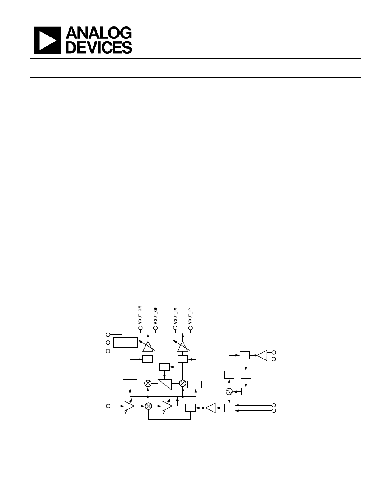
FUNCTIONAL BLOCK DIAGRAM
SCANOUT
DATA
CLK
INTERFACE
SERIAL
BBVGA
MUX
÷2
MUX
DISCR
FM
90°
0°
AMDET
RFIN
LNA
AMP IF
×3
HMC6301
PFD
REFCLK_M
REFCLK_P
DIV CP
LPF
MUX
EXTLO_N
EXTLO_P
Figure 1.
Rev. A
Document Feedback
Information furnished by Analog Devices is believed to be accurate and reliable. However, no
responsibility is assumed by Analog Devices for its use, nor for any infringements of patents or other
rights of third parties that may result from its use. Specifications subject to change without notice. No
license is granted by implication or otherwise under any patent or patent rights of Analog Devices.
Trademarksandregisteredtrademarksarethepropertyoftheirrespectiveowners.
One Technology Way, P.O. Box 9106, Norwood, MA 02062-9106, U.S.A.
Tel: 781.329.4700
©2016 Analog Devices, Inc. All rights reserved.
Technical Support
www.analog.com
1 page 
HMC6301
RECOMMENDED OPERATING CONDITIONS
Table 2.
Parameter
POWER SUPPLY
Buffer
Low Noise Amplifier (LNA)
Tripler
Divider
Voltage Controlled Oscillator (VCO)
Intermediate Frequency
Mixer
Synthesizer
Digital Circuit
INPUT VOLTAGE RANGE
Serial Digital Interface
Logic High
Logic Low
REFERENCE CLOCK
Reference Clock, Positive
LVPECL/LVDS
CMOS
Reference Clock, Negative
LVPECL/LVDS
CMOS
BASEBAND I/Q
In-Phase Baseband Input
Negative (Minus)
Positive
Quadrature Baseband Input
Negative (Minus)
Positive
BASEBAND I/Q, COMMON MODE
In-Phase Baseband Input
Negative (Minus)
Positive
Quadrature Baseband Input
Negative (Minus)
Positive
ANALOG GAIN CONTROL
Low Noise Amplifier
IF Variable Gain Amplifier
EXTERNAL LO
Positive
Negative
DRAIN CURRENT
1.35 V
2.7 V
Symbol
VCCBUF
VDDLNA
VCCTRIP
VCCDIV
VCCVCO
VCCIF
VCCMIX
VCCSYN
VDDD
DATA, ENABLE, CLK, RESET
REFCLKP
REFCLKN
VOUT_IM
VOUT_IP
VOUT_QM
VOUT_QP
VOUT_IM
VOUT_IP
VOUT_QM
VOUT_QP
ANACTRLLNA
ACTLIFVGA
EXTLO_P
EXTLO_N
Data Sheet
Min Typ
2.565
2.565
2.565
2.565
2.565
2.565
2.565
1.3
1.3
2.7
2.7
2.7
2.7
2.7
2.7
2.7
1.35
1.35
Max Unit
2.835
2.835
2.835
2.835
2.835
2.835
2.835
1.48
1.48
V dc
V dc
V dc
V dc
V dc
V dc
V dc
V dc
V dc
0.9
−0.05
1.2
+0.1
1.4 V
+0.3 V
3.3/2.5
1.2
3.3/2.5
1.2
V
V
V
V
10 50
10 50
10 50
10 50
200 mV p-p
200 mV p-p
200 mV p-p
200 mV p-p
1.3
1.3
1.3
1.3
0.1
0.1
03
03
<1
300
V
V
V
V
2.0 V
2.25 V
6 dBm
6 dBm
mA
mA
Rev. A | Page 4 of 24
5 Page 
HMC6301
0
5
10
15
20
25
30
35
+85°C
+25°C
–40°C
40
0 6 12 18 24 30 36
ATTENUATION SETTING
Figure 9. Baseband Attenuation vs. Attenuation Setting over
Temperature, Measurement Taken at 60 GHz
0
–5
–10
–15
–20
–25
–30
–35
+85°C
+25°C
–40°C
–40
57 58 59 60 61 62 63 64
FREQUENCY (GHz)
Figure 10. Input IP3 (IIP3) vs. Frequency over Temperature,
Minimum LNA Gain, Measurement Taken at
Maximum IF Gain and Maximum Baseband Attenuation
0
+85°C
–5
+25°C
–40°C
–10
–15
–20
–25
–30
–35
–40
57 58 59 60 61 62 63 64
FREQUENCY (GHz)
Figure 11. Input IP3 (IIP3) vs. Frequency over Temperature,
Minimum LNA Gain, Measurement Taken at
Maximum IF Gain and Maximum Baseband Attenuation
Data Sheet
40
35
30
25
20
15
10
5
+85°C
+25°C
–40°C
0
57 58 59 60 61 62 63 64
FREQUENCY (GHz)
Figure 12. Sideband Suppression vs. Frequency over Temperature,
Measurement Taken at Maximum Gain
16
+85°C
14
+25°C
–40°C
12
10
8
6
4
2
0
57 58 59 60 61 62 63 64
FREQUENCY (GHz)
Figure 13. Noise Figure vs. Frequency over Temperature
32
16
8
4
2
1
–40 –27 –14 –1 12 25 38 51 64 77 90
TEMPERATURE (°C)
Figure 14. Temperature Sensor Reading vs. Temperature
Rev. A | Page 10 of 24
11 Page | ||
| Páginas | Total 25 Páginas | |
| PDF Descargar | [ Datasheet HMC6301.PDF ] | |
Hoja de datos destacado
| Número de pieza | Descripción | Fabricantes |
| HMC6300 | 60 GHz Millimeterwave Transmitter | Analog Devices |
| HMC6301 | Millimeterwave Receiver | Analog Devices |
| HMC630LP3 | GaAs HBT VECTOR MODULATOR | Analog Devices |
| HMC630LP3E | GaAs HBT VECTOR MODULATOR | Analog Devices |
| Número de pieza | Descripción | Fabricantes |
| SLA6805M | High Voltage 3 phase Motor Driver IC. |
Sanken |
| SDC1742 | 12- and 14-Bit Hybrid Synchro / Resolver-to-Digital Converters. |
Analog Devices |
|
DataSheet.es es una pagina web que funciona como un repositorio de manuales o hoja de datos de muchos de los productos más populares, |
| DataSheet.es | 2020 | Privacy Policy | Contacto | Buscar |