|
|
|
PDF ADAU1361 Data sheet ( Hoja de datos )
| Número de pieza | ADAU1361 | |
| Descripción | 24-Bit Audio Codec | |
| Fabricantes | Analog Devices | |
| Logotipo | ||
Hay una vista previa y un enlace de descarga de ADAU1361 (archivo pdf) en la parte inferior de esta página. Total 30 Páginas | ||
|
No Preview Available !
Stereo, Low Power, 96 kHz, 24-Bit
Audio Codec with Integrated PLL
ADAU1361
FEATURES
GENERAL DESCRIPTION
24-bit stereo audio ADC and DAC: >98 dB SNR
Sampling rates from 8 kHz to 96 kHz
Low power: 7 mW record, 7 mW playback, 48 kHz at 1.8 V
6 analog input pins, configurable for single-ended or
differential inputs
Flexible analog input/output mixers
Stereo digital microphone input
Analog outputs: 2 differential stereo, 2 single-ended stereo,
1 mono headphone output driver
PLL supporting input clocks from 8 MHz to 27 MHz
Analog automatic level control (ALC)
Microphone bias reference voltage
Analog and digital I/O: 1.8 V to 3.65 V
I2C and SPI control interfaces
Digital audio serial data I/O: stereo and time-division
multiplexing (TDM) modes
Software-controllable clickless mute
Software power-down
32-lead, 5 mm × 5 mm LFCSP
−40°C to +85°C operating temperature range
APPLICATIONS
Smartphones/multimedia phones
Digital still cameras/digital video cameras
Portable media players/portable audio players
Phone accessories products
The ADAU1361 is a low power, stereo audio codec that supports
stereo 48 kHz record and playback at 14 mW from a 1.8 V analog
supply. The stereo audio ADCs and DACs support sample rates
from 8 kHz to 96 kHz as well as a digital volume control. The
ADAU1361 is ideal for battery-powered audio and telephony
applications.
The record path includes an integrated microphone bias circuit
and six inputs. The inputs can be mixed and muxed before the
ADC, or they can be configured to bypass the ADC. The
ADAU1361 includes a stereo digital microphone input.
The ADAU1361 includes five high power output drivers (two
differential and three single-ended), supporting stereo head-
phones, an earpiece, or other output transducer. AC-coupled
or capless configurations are supported. Individual fine level
controls are supported on all analog outputs. The output mixer
stage allows for flexible routing of audio.
The serial control bus supports the I2C and SPI protocols. The
serial audio bus is programmable for I2S, left-/right-justified,
and TDM modes. A programmable PLL supports flexible clock
generation for all standard integer rates and fractional master
clocks from 8 MHz to 27 MHz.
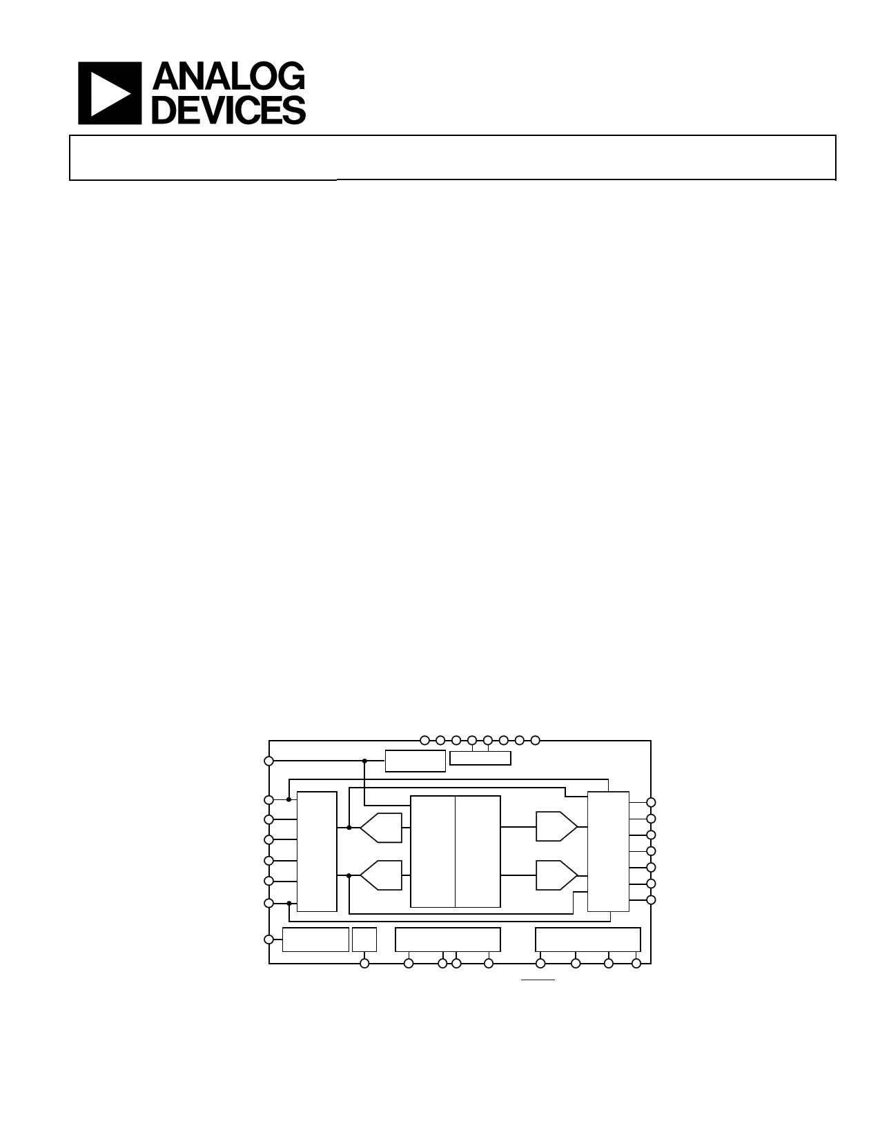
FUNCTIONAL BLOCK DIAGRAM
JACKDET/MICIN
HP JACK REGULATOR
DETECTION
ADAU1361
LAUX
LINP
LINN
RINP
RINN
RAUX
INPUT
MIXERS
ALC
ADC
ADC
ADC
DAC
DIGITAL DIGITAL
FILTERS FILTERS
DAC
DAC
OUTPUT
MIXERS
LOUTP
LOUTN
LHP
MONOOUT
RHP
ROUTP
ROUTN
MICBIAS
MICROPHONE
BIAS
PLL
SERIAL DATA
INPUT/OUTPUT PORTS
I2C/SPI
CONTROL PORT
MCLK ADC_SDATA
DAC_SDATA ADDR0/ ADDR1/ SCL/ SDA/
CLATCH CDATA CCLK COUT
Figure 1.
Rev. C
Information furnished by Analog Devices is believed to be accurate and reliable. However, no
responsibility is assumed by Analog Devices for its use, nor for any infringements of patents or other
rights of third parties that may result from its use. Specifications subject to change without notice. No
license is granted by implication or otherwise under any patent or patent rights of Analog Devices.
Trademarksandregisteredtrademarksarethepropertyoftheirrespectiveowners.
One Technology Way, P.O. Box 9106, Norwood, MA 02062-9106, U.S.A.
Tel: 781.329.4700
www.analog.com
Fax: 781.461.3113 ©2009–2010 Analog Devices, Inc. All rights reserved.
1 page 
ADAU1361
SPECIFICATIONS
Supply voltage (AVDD) = 3.3 V, TA = 25°C, master clock = 12.288 MHz (48 kHz fS, 256 × fS mode), input sample rate = 48 kHz, measurement
bandwidth = 20 Hz to 20 kHz, word width = 24 bits, CLOAD (digital output) = 20 pF, ILOAD (digital output) = 2 mA, VIH = 2 V, VIL = 0.8 V,
unless otherwise noted. Performance of all channels is identical, exclusive of the interchannel gain mismatch and interchannel phase
deviation specifications.
ANALOG PERFORMANCE SPECIFICATIONS
Specifications guaranteed at 25°C (ambient).
Table 1.
Parameter
ANALOG-TO-DIGITAL CONVERTERS
ADC Resolution
Digital Attenuation Step
Digital Attenuation Range
INPUT RESISTANCE
Single-Ended Line Input
PGA Inverting Inputs
PGA Noninverting Inputs
SINGLE-ENDED LINE INPUT
Full-Scale Input Voltage (0 dB)
Dynamic Range
With A-Weighted Filter (RMS)
No Filter (RMS)
Total Harmonic Distortion + Noise
Signal-to-Noise Ratio
With A-Weighted Filter (RMS)
No Filter (RMS)
Gain per Step
Total Gain Range
Mute Attenuation
Interchannel Gain Mismatch
Offset Error
Gain Error
Interchannel Isolation
Power Supply Rejection Ratio
Test Conditions/Comments
ADC performance excludes mixers
and PGA
All ADCs
−12 dB gain
0 dB gain
6 dB gain
−12 dB gain
0 dB gain
35.25 dB gain
All gains
Scales linearly with AVDD
AVDD = 1.8 V
AVDD = 3.3 V
20 Hz to 20 kHz, −60 dB input
AVDD = 1.8 V
AVDD = 3.3 V
AVDD = 1.8 V
AVDD = 3.3 V
−1 dBFS
AVDD = 1.8 V
AVDD = 3.3 V
AVDD = 1.8 V
AVDD = 3.3 V
AVDD = 1.8 V
AVDD = 3.3 V
CM capacitor = 20 μF
100 mV p-p @ 217 Hz
100 mV p-p @ 1 kHz
Min
−12
Typ Max
24
0.375
95
83
21
10.5
84.5
53
2
105
AVDD/3.3
0.55 (1.56)
1.0 (2.83)
94
99
91
96
−88
−90
94
99
91
96
3
−87
0.005
0
−12
68
+6
65
67
Unit
Bits
dB
dB
kΩ
kΩ
kΩ
kΩ
kΩ
kΩ
kΩ
V rms
V rms (V p-p)
V rms (V p-p)
dB
dB
dB
dB
dB
dB
dB
dB
dB
dB
dB
dB
dB
dB
mV
%
dB
dB
dB
Rev. C | Page 4 of 80
5 Page 
ADAU1361
DIGITAL FILTERS
Table 5.
Parameter
ADC DECIMATION FILTER
Pass Band
Pass-Band Ripple
Transition Band
Stop Band
Stop-Band Attenuation
Group Delay
DAC INTERPOLATION FILTER
Pass Band
Pass-Band Ripple
Transition Band
Stop Band
Stop-Band Attenuation
Group Delay
Mode
All modes, typ @ 48 kHz
48 kHz mode, typ @ 48 kHz
96 kHz mode, typ @ 96 kHz
48 kHz mode, typ @ 48 kHz
96 kHz mode, typ @ 96 kHz
48 kHz mode, typ @ 48 kHz
96 kHz mode, typ @ 96 kHz
48 kHz mode, typ @ 48 kHz
96 kHz mode, typ @ 96 kHz
48 kHz mode, typ @ 48 kHz
96 kHz mode, typ @ 96 kHz
48 kHz mode, typ @ 48 kHz
96 kHz mode, typ @ 96 kHz
Factor
0.4375 fS
0.5 fS
0.5625 fS
22.9844/fS
0.4535 fS
0.3646 fS
0.5 fS
0.5 fS
0.5465 fS
0.6354 fS
25/fS
11/fS
Min Typ
Max Unit
21
±0.015
24
27
67
479
kHz
dB
kHz
kHz
dB
μs
22 kHz
35 kHz
±0.01 dB
±0.05 dB
24 kHz
48 kHz
26 kHz
61 kHz
69 dB
68 dB
521 μs
115 μs
DIGITAL INPUT/OUTPUT SPECIFICATIONS
−40°C < TA < +85°C, IOVDD = 3.3 V ± 10%.
Table 6.
Parameter
INPUT SPECIFICATIONS
Input Voltage High (VIH)
Input Voltage Low (VIL)
Input Leakage
Pull-Ups/Pull-Downs Disabled
Pull-Ups Enabled
Pull-Downs Enabled
Input Capacitance
OUTPUT SPECIFICATIONS
Output Voltage High (VOH)
Output Voltage Low (VOL)
Test Conditions/Comments
IIH @ VIH = 3.3 V
IIL @ VIL = 0 V
IIL @ VIL = 0 V (MCLK pin)
IIH @ VIH = 3.3 V
IIL @ VIL = 0 V
IIH @ VIH = 3.3 V
IIL @ VIL = 0 V
IOH = 2 mA @ 3.3 V, 0.85 mA @ 1.8 V
IOL = 2 mA @ 3.3 V, 0.85 mA @ 1.8 V
Min Typ
0.7 × IOVDD
−0.17
−0.17
−13.5
−0.7
−13.5
2.7
−0.18
0.8 × IOVDD
Max Unit
V
0.3 × IOVDD V
+0.17
+0.17
−0.5
+0.7
−0.5
8.3
+0.18
5
μA
μA
μA
μA
μA
μA
μA
pF
V
0.1 × IOVDD V
Rev. C | Page 10 of 80
11 Page | ||
| Páginas | Total 30 Páginas | |
| PDF Descargar | [ Datasheet ADAU1361.PDF ] | |
Hoja de datos destacado
| Número de pieza | Descripción | Fabricantes |
| ADAU1361 | 24-Bit Audio Codec | Analog Devices |
| Número de pieza | Descripción | Fabricantes |
| SLA6805M | High Voltage 3 phase Motor Driver IC. |
Sanken |
| SDC1742 | 12- and 14-Bit Hybrid Synchro / Resolver-to-Digital Converters. |
Analog Devices |
|
DataSheet.es es una pagina web que funciona como un repositorio de manuales o hoja de datos de muchos de los productos más populares, |
| DataSheet.es | 2020 | Privacy Policy | Contacto | Buscar |