|
|
|
PDF NSBC114EPDXV6 Data sheet ( Hoja de datos )
| Número de pieza | NSBC114EPDXV6 | |
| Descripción | Complementary Bias Resistor Transistors | |
| Fabricantes | ON Semiconductor | |
| Logotipo | ||
Hay una vista previa y un enlace de descarga de NSBC114EPDXV6 (archivo pdf) en la parte inferior de esta página. Total 10 Páginas | ||
|
No Preview Available !
MUN5311DW1,
NSBC114EPDXV6,
NSBC114EPDP6
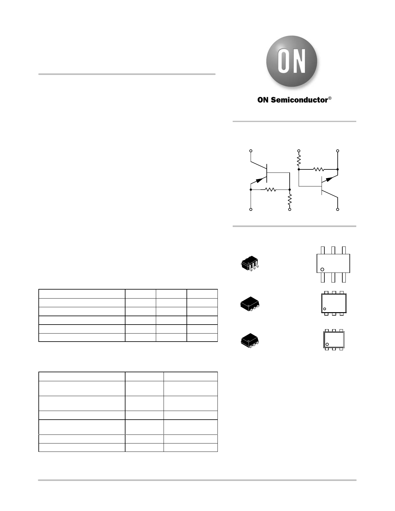
Complementary Bias
Resistor Transistors
R1 = 10 kW, R2 = 10 kW
NPN and PNP Transistors with Monolithic
Bias Resistor Network
This series of digital transistors is designed to replace a single
device and its external resistor bias network. The Bias Resistor
Transistor (BRT) contains a single transistor with a monolithic bias
network consisting of two resistors; a series base resistor and a
base-emitter resistor. The BRT eliminates these individual
components by integrating them into a single device. The use of a BRT
can reduce both system cost and board space.
Features
• Simplifies Circuit Design
• Reduces Board Space
• Reduces Component Count
• S and NSV Prefix for Automotive and Other Applications
Requiring Unique Site and Control Change Requirements;
AEC-Q101 Qualified and PPAP Capable*
• These Devices are Pb-Free, Halogen Free/BFR Free and are RoHS
Compliant
MAXIMUM RATINGS
(TA = 25°C both polarities Q1 (PNP) & Q2 (NPN), unless otherwise noted)
Rating
Symbol
Max
Unit
Collector-Base Voltage
VCBO
50
Vdc
Collector-Emitter Voltage
VCEO
50
Vdc
Collector Current − Continuous
IC 100 mAdc
Input Forward Voltage
VIN(fwd)
40
Vdc
Input Reverse Voltage
VIN(rev)
10
Vdc
Stresses exceeding those listed in the Maximum Ratings table may damage the
device. If any of these limits are exceeded, device functionality should not be
assumed, damage may occur and reliability may be affected.
ORDERING INFORMATION
Device
Package
Shipping†
MUN5311DW1T1G,
SMUN5311DW1T1G*
SOT−363
3,000/Tape & Reel
MUN5311DW1T2G,
SMUN5311DW1T2G*
SOT−363
3,000/Tape & Reel
SMUN5311DW1T3G
SOT−363 10,000/Tape & Reel
NSBC114EPDXV6T1G,
NSVBC114EPDXV6T1G*
SOT−563
4,000/Tape & Reel
NSBC114EPDXV6T5G
SOT−563
8,000/Tape & Reel
NSBC114EPDP6T5G
SOT−963
8,000/Tape & Reel
†For information on tape and reel specifications, including part orientation and
tape sizes, please refer to our Tape and Reel Packaging Specifications
Brochure, BRD8011/D.
© Semiconductor Components Industries, LLC, 2014
May, 2014 − Rev. 2
1
http://onsemi.com
PIN CONNECTIONS
(3) (2) (1)
R1
Q1
R2 R1
(4) (5)
R2
Q2
(6)
MARKING DIAGRAMS
SOT−363
CASE 419B
6
11 M G
G
1
SOT−563
CASE 463A
11 M G
G
1
SOT−963
CASE 527AD
LMG
G
1
11/L = Specific Device Code
M = Date Code*
G = Pb-Free Package
(Note: Microdot may be in either location)
*Date Code orientation may vary depending up-
on manufacturing location.
Publication Order Number:
DTC114EP/D
1 page 
MUN5311DW1, NSBC114EPDXV6, NSBC114EPDP6
TYPICAL CHARACTERISTICS − PNP TRANSISTOR
MUN5311DW1, NSBC114EPDXV6
1
IC/IB = 10
0.1
1000
TA = −25°C
75°C
25°C
100
VCE = 10 V
TA = 75°C
−25°C
25°C
0.01
0
10
9
8
7
6
5
4
3
2
1
0
0
20 40 60
IC, COLLECTOR CURRENT (mA)
Figure 7. VCE(sat) vs. IC
10
80 1
10
IC, COLLECTOR CURRENT (mA)
Figure 8. DC Current Gain
100
f = 10 kHz
lE = 0 A
TA = 25°C
100
75°C 25°C
TA = −25°C
10
1
0.1
10 20 30 40
VR, REVERSE VOLTAGE (V)
Figure 9. Output Capacitance
0.01
VO = 5 V
0.001
50 0 1 2 3 4 5 6 7 8 9 10
Vin, INPUT VOLTAGE (V)
Figure 10. Output Current vs. Input Voltage
100
VO = 0.2 V
10 TA = −25°C
25°C
75°C
1
0.1
0
10
20 30
40 50
IC, COLLECTOR CURRENT (mA)
Figure 11. Input Voltage vs. Output Current
http://onsemi.com
5
5 Page | ||
| Páginas | Total 10 Páginas | |
| PDF Descargar | [ Datasheet NSBC114EPDXV6.PDF ] | |
Hoja de datos destacado
| Número de pieza | Descripción | Fabricantes |
| NSBC114EPDXV6 | Complementary Bias Resistor Transistors | ON Semiconductor |
| NSBC114EPDXV6T1 | Dual Bias Resistor Transistors | ON Semiconductor |
| NSBC114EPDXV6T5 | Dual Bias Resistor Transistors | ON Semiconductor |
| Número de pieza | Descripción | Fabricantes |
| SLA6805M | High Voltage 3 phase Motor Driver IC. |
Sanken |
| SDC1742 | 12- and 14-Bit Hybrid Synchro / Resolver-to-Digital Converters. |
Analog Devices |
|
DataSheet.es es una pagina web que funciona como un repositorio de manuales o hoja de datos de muchos de los productos más populares, |
| DataSheet.es | 2020 | Privacy Policy | Contacto | Buscar |