|
|
|
PDF AD8305 Data sheet ( Hoja de datos )
| Número de pieza | AD8305 | |
| Descripción | Logarithmic Converter | |
| Fabricantes | Analog Devices | |
| Logotipo | ||
1. AD8305 Hay una vista previa y un enlace de descarga de AD8305 (archivo pdf) en la parte inferior de esta página. Total 25 Páginas | ||
|
No Preview Available !
FEATURES
Optimized for fiber optic photodiode interfacing
Measures current over 5 decades
Law conformance 0.1 dB from 10 nA to 1 mA
Single- or dual-supply operation (3 V to 12 V total)
Full log-ratio capabilities
Nominal slope of 10 mV/dB (200 mV/decade)
Nominal intercept of 1 nA (set by external resistor)
Optional adjustment of slope and intercept
Complete and temperature stable
Rapid response time for a given current level
Miniature 16-lead chip scale package
(LFCSP 3 mm × 3 mm)
Low power: ~5 mA quiescent current
APPLICATIONS
Optical power measurement
Wide range baseband logarithmic compression
Measurement of current and voltage ratios
Optical absorbance measurement
GENERAL DESCRIPTION
The AD83051 is an inexpensive microminiature logarithmic converter
optimized for determining optical power in fiber optic systems. It uses
an advanced implementation of a classic translinear (junction based)
technique to provide a large dynamic range in a versatile and easily
used form. A single-supply voltage of between 3 V and 12 V is
adequate; dual supplies may optionally be used. The low quiescent
current (typically 5 mA) permits use in battery-operated applications.
The input current, IPD, of 10 nA to 1 mA applied to the INPT pin is the
collector current of an optimally scaled NPN transistor, which converts
this current to a voltage (VBE) with a precise logarithmic relationship. A
second such converter is used to handle the reference current (IREF)
applied to pin IREF. These input nodes are biased slightly above ground
(0.5 V). This is generally acceptable for photodiode applications where
the anode does not need to be grounded. Similarly, this bias voltage is
easily accounted for in generating IREF. The output of the logarithmic
front end is available at Pin VLOG.
The basic logarithmic slope at this output is nominally 200 mV/decade
(10 mV/dB). Thus, a 100 dB range corresponds to an output change of
1 V. When this voltage (or the buffer output) is applied to an ADC that
permits an external reference voltage to be employed, the AD8305
voltage reference output of 2.5 V at Pin VREF can be used to improve
the scaling accuracy. Suitable ADCs include the AD7810 (serial 10-bit),
AD7823 (serial 8-bit), and AD7813 (parallel, 8-bit or 10-bit). Other
values of the logarithmic slope can be provided using a simple external
resistor network.
1 Protected by U.S. Patent No. 5,519,308.
Rev. B
Information furnished by Analog Devices is believed to be accurate and reliable. However, no
responsibility is assumed by Analog Devices for its use, nor for any infringements of patents or other
rights of third parties that may result from its use. Specifications subject to change without notice. No
license is granted by implication or otherwise under any patent or patent rights of Analog Devices.
Trademarksandregisteredtrademarksarethepropertyoftheirrespectiveowners.
100 dB Range (10 nA to 1 mA)
Logarithmic Converter
AD8305
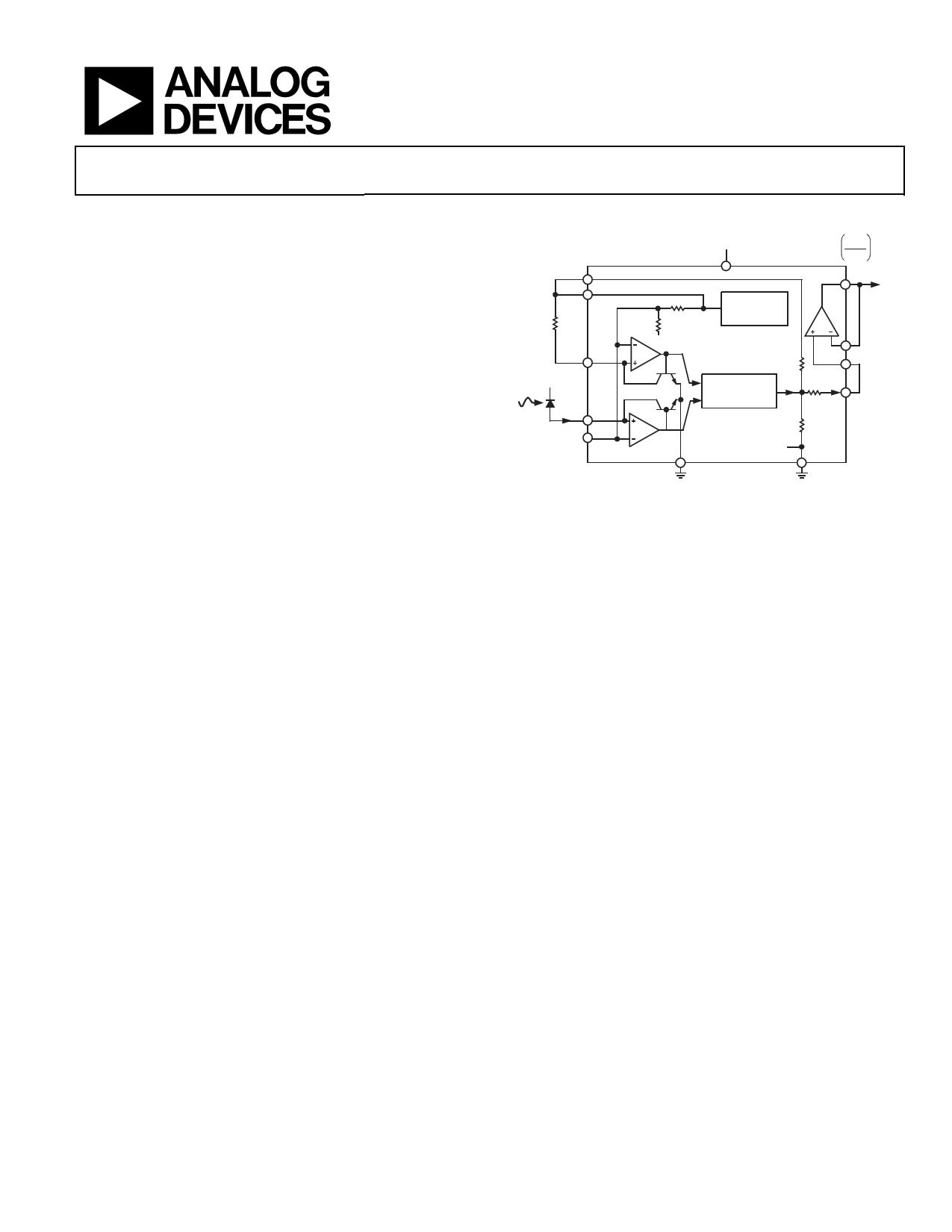
FUNCTIONAL BLOCK DIAGRAM
VRDZ
VP
VPOS
IPD
0.20 log10 1nA
VOUT
VREF
200kΩ
0.5V
IREF
VBIAS
IPD
INPT
20kΩ
80kΩ
2.5V
BIAS
GENERATOR
COMM
Q2
Q1
SCAL
VBE2
14.2kΩ
–
TEMPERATURE
ILOG
BFIN
451Ω
+ COMPENSATION
VLOG
VBE1
6.69kΩ
VSUM 0.5V
COMM
VNEG
Figure 1.
COMM
The logarithmic intercept (also known as the reference current) is
nominally positioned at 1 nA by the use of the externally generated
current, IREF, of 10 μA, provided by a 200 kΩ resistor connected
between VREF, at 2.5 V, and the reference input, IREF, at 0.5 V. The
intercept can be adjusted over a wide range by varying this resistor.
The AD8305 can also operate in a log ratio mode, with the numerator
current applied to INPT and the denominator current applied to IREF.
A buffer amplifier is provided for driving a substantial load, for use in
raising the basic slope of 10 mV/dB to higher values, as a precision
comparator (threshold detector), or in implementing low-pass filters.
Its rail-to-rail output stage can swing to within 100 mV of the positive
and negative supply rails, and its peak current sourcing capacity is
25 mA.
It is a fundamental aspect of translinear logarithmic converters that the
small signal bandwidth falls as the current level diminishes, and the
low frequency noise-spectral density increases. At the 10 nA level, the
bandwidth of the AD8305 is about 50 kHz and increases in proportion
to IPD up to a maximum value of about 15 MHz. Using the buffer
amplifier, the increase in noise level at low currents can be addressed by
using it to realize lowpass filters of up to three poles.
The AD8305 is available in a 16-lead LFCSP package and is specified
for operation from −40°C to +85°C.
One Technology Way, P.O. Box 9106, Norwood, MA 02062-9106, U.S.A.
Tel: 781.329.4700
www.analog.com
Fax: 781.461.3113 ©2003–2010 Analog Devices, Inc. All rights reserved.
1 page 
AD8305
ABSOLUTE MAXIMUM RATINGS
Table 2.
Parameter
Supply Voltage VP − VN
Input Current
Internal Power Dissipation
θJA1
Maximum Junction Temperature
Operating Temperature Range
Storage Temperature Range
Lead Temperature (Soldering 60 sec)
Rating
12 V
20 mA
500 mW
30°C/W
125°C
−40°C to +85°C
−65°C to +150°C
300°C
1 With package die paddle soldered to thermal pad containing nine vias
connected to inner and bottom layers.
Stresses above those listed under Absolute Maximum Ratings
may cause permanent damage to the device. This is a stress
rating only; functional operation of the device at these or any
other conditions above those indicated in the operational
section of this specification is not implied. Exposure to absolute
maximum rating conditions for extended periods may affect
device reliability.
ESD CAUTION
Rev. B | Page 4 of 24
5 Page 
AD8305
10
8
6
4
MEAN + 3σ
2
0
–2
MEAN – 3σ
–4
–6
–8
–10
–40 –30 –20 –10 0 10 20 30 40 50 60 70 80 90
TEMPERATURE (°C)
Figure 27. Slope Drift vs. Temperature (3σ to Either Side of Mean of
200 mV/decade)
350
250
MEAN + 3σ
150
50
–50
–150
–250
MEAN – 3σ
–350–40 –30 –20 –10 0 10 20 30 40 50 60 70 808590
TEMPERATURE (°C)
Figure 28. Intercept Drift vs. Temperature (3σ to Either Side of Mean of 1 nA)
6000
5000
4000
3000
2000
1000
0
190 195 200 205 210
SLOPE (mV/dec)
Figure 29. Distribution of Logarithmic Slope (Nominally
200 mV/decade) Sample >22,000
4000
3500
3000
2500
2000
1500
1000
500
0
0.4 0.6 0.8 1.0 1.2 1.4 1.6
INTERCEPT (nA)
Figure 30. Distribution of Logarithmic Intercept (Nominally 1 nA when
RREF = 200 kΩ ± 0.1%) Sample >22,000
7000
6000
5000
4000
3000
2000
1000
0
2.44
2.46
2.48
2.50
VREF (V)
2.52
2.54 2.56
Figure 31. Distribution of VREF (RL = 100 kΩ) Sample >22,000
6000
5000
4000
3000
2000
1000
0
–0.015
–0.010
–0.005
0
0.005
VINPT – VSUM VOLTAGE (V)
0.010
0.015
Figure 32. Distribution of Offset Voltage (VINPT − VSUM) Sample >22,000
Rev. B | Page 10 of 24
11 Page | ||
| Páginas | Total 25 Páginas | |
| PDF Descargar | [ Datasheet AD8305.PDF ] | |
Hoja de datos destacado
| Número de pieza | Descripción | Fabricantes |
| AD830 | High Speed Video Difference Amplifier | Analog Devices |
| AD8300 | +3 Volt/ Serial Input Complete 12-Bit DAC | Analog Devices |
| AD8302 | RF/IF Gain and Phase Detector | Analog Devices |
| AD8303 | +3 V/ Dual/ Serial Input Complete 12-Bit DAC | Analog Devices |
| Número de pieza | Descripción | Fabricantes |
| SLA6805M | High Voltage 3 phase Motor Driver IC. |
Sanken |
| SDC1742 | 12- and 14-Bit Hybrid Synchro / Resolver-to-Digital Converters. |
Analog Devices |
|
DataSheet.es es una pagina web que funciona como un repositorio de manuales o hoja de datos de muchos de los productos más populares, |
| DataSheet.es | 2020 | Privacy Policy | Contacto | Buscar |