|
|
|
PDF MAX14824 Data sheet ( Hoja de datos )
| Número de pieza | MAX14824 | |
| Descripción | IO-Link Master Transceiver | |
| Fabricantes | Maxim Integrated | |
| Logotipo | ||
Hay una vista previa y un enlace de descarga de MAX14824 (archivo pdf) en la parte inferior de esta página. Total 28 Páginas | ||
|
No Preview Available !
19-5788; Rev 3; 5/12
EVALUATION KIT AVAILABLE
MAX14824
IO-Link Master Transceiver
General Description
The MAX14824 is an IO-LinkM master interface that inte-
grates an IO-Link physical layer transceiver with an
auxiliary digital input and two linear regulators. High port
count IO-Link master applications are supported through
in-band SPI addressing, and the 12MHz SPI interface
minimizes host controller access times. In-band address-
ing and selectable SPI addresses enable cascading up
to 16 devices.
The device supports all the IO-Link data rates and fea-
tures slew-rate-controlled drivers to reduce EMI. The
driver is guaranteed to drive up to 300mA (min) load
currents. Internal wake-up circuitry automatically deter-
mines the correct wake-up polarity, allowing for the use
of simple UARTs for wake-up pulse generation.
The MAX14824 is available in a 4mm x 4mm, 24-pin
TQFN package with exposed pad, and operates over the
extended -40NC to +105NC temperature range.
Applications
IO-Link Master Controllers
PLC Fieldbus Gateways
High Port Count IO-Link Masters
24V Digital Inputs and Outputs
Ordering Information appears at end of data sheet.
Features
S IO-Link v.1.0 and v.1.1 Physical Layer Compliant
S Supports COM1, COM2, and COM3 Data Rates
S Push-Pull, High-Side, or Low-Side Outputs
S 300mA C/Q Output Drive
S 1µF C/Q Load Drive Capability
S Generates 500mA Wake-Up Pulse
S Automatic Wake-Up Pulse Polarity
S Auxiliary Digital Input
S 5V and 3.3V Linear Regulators
S SPI Interface for Configuration and Monitoring
S SPI-Based Chip Addressing
S EMI Emission Control Through Slew-Controlled
Driver
S Reverse-Polarity Protection on DI
S Short-Circuit Protection on C/Q
S High Temperature Warning and Thermal Shutdown
S Extensive Fault Monitoring and Reporting
S -40NC to +105NC Operating Temperature Range
S 4mm x 4mm TQFN Package
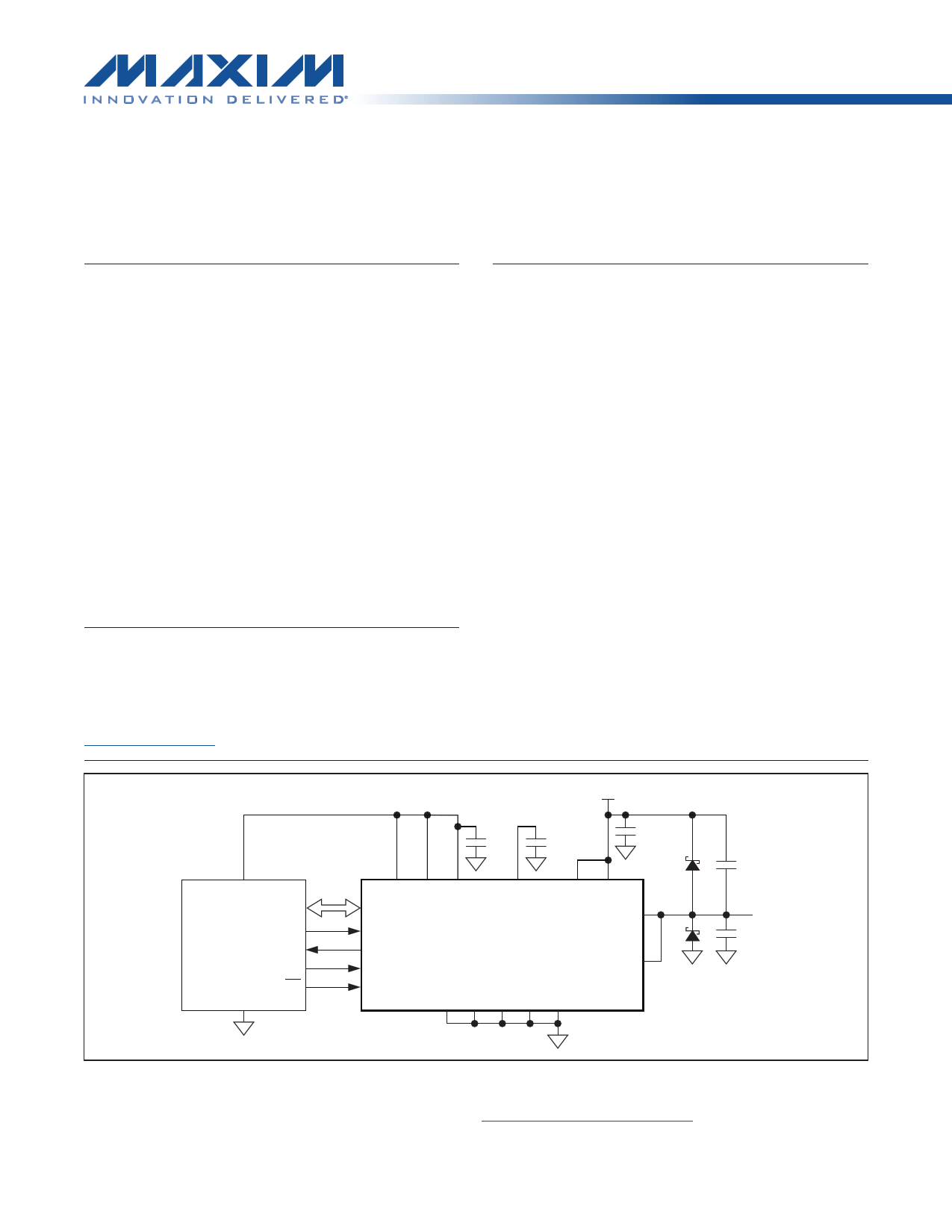
Typical Operating Circuits
24V
1μF 0.1μF
1μF
VCC SPI VL TXQ LDO33 V5 LDOIN VCC
IO-LINK
CONTROLLER
GPO
RX
TX
WUEN
RX
TXC
MAX14824
C/Q
DI
RTS
GND
TXEN
A0 A1 A2 A3 GND
270pF
C/Q
270pF
Typical Operating Circuits continued at end of data sheet.
IO-Link is a registered trademark of Profibus User Organization (PNO).
For related parts and recommended products to use with this part, refer to: www.maxim-ic.com/MAX14824.related
1
For pricing, delivery, and ordering information, please contact Maxim Direct at 1-888-629-4642,
or visit Maxim’s website at www.maxim-ic.com.
1 page 
MAX14824
IO-Link Master Transceiver
DC ELECTRICAL CHARACTERISTICS (continued)
(VCC = 18V to 36V, VL = 2.3V to 5.5V, VGND = 0V; all logic inputs at VL or GND; TA = -40°C to +105°C, unless otherwise noted. Typical
values are at VCC = 24V, VL = 3.3V, and TA = +25NC, unless otherwise noted.) (Note 2)
PARAMETER
SYMBOL
CONDITIONS
LOGIC INPUTS (TXC, TXQ, TXEN, CS, WUEN, SDI, SCLK, A3, A2, A1, A0)
Logic Input-Voltage Low
VIL
Logic Input-Voltage High
VIH
Logic Input Leakage Current
Logic Input Capacitance
A1 Pulldown Resistance
ILEAK
CIN
RA1PD
Logic input = GND or VL
LOGIC OUTPUTS (RX, LI, UV, SDO, IRQ)
Logic Output-Voltage Low
VOL
IOUT = -5mA
Logic Output-Voltage High
VOHRX,
VOHWU, VOHLI,
VOHSDO,
VOHIRQ,
IOUT = 5mA (Note 3)
SDO Leakage Current
THERMAL SHUTDOWN
ILK_SDO
SDO disabled, SDO = GND or VL
Thermal Warning Threshold
Die temperature rising, OTemp bit is set
Thermal Warning Threshold
Hysteresis
Die temperature falling, OTemp bit is
cleared
Thermal Shutdown Threshold
Die temperature rising
Thermal Shutdown Hysteresis
MIN TYP MAX UNITS
0.3 x
VL
V
0.7 x
VL
V
-1 +1 FA
5 pF
325 800 kI
0.4 V
VL -
0.6
V
-1 +1 FA
+115
20
+150
20
NC
NC
NC
NC
AC ELECTRICAL CHARACTERISTICS
(VCC = 18V to 36V, VL = 2.3V to 5.5V, VGND = 0V; all logic inputs at VL or GND; TA = -40°C to +105°C, unless otherwise noted. Typical
values are at VCC = 24V, VL = 3.3V, and TA = +25oC, unless otherwise noted.) (Note 2)
PARAMETER
C/Q, DI INTERFACES
Data Rate
DRIVER (C/Q)
Driver Low-to-High Propagation
Delay
Driver High-to-Low Propagation
Delay
SYMBOL
CONDITIONS
HiSlew = 1
DR HiSlew = 0
tPDLH
tPDHL
Push-pull or high-side
(PNP) configuration,
Figure 1
Push-pull or low-side
(NPN) configuration,
Figure 1
HiSlew = 1
HiSlew = 0
HiSlew = 1
HiSlew = 0
MIN TYP MAX UNITS
4.8 230.4
4.8
38.4
kbps
0.5 2
1.6 5
0.5 2
1.6 5
Fs
Fs
5
5 Page 
MAX14824
IO-Link Master Transceiver
Typical Operating Characteristics
(VCC = 24V, LDOIN = VCC, VL = LDO33, C/Q is in push-pull configuration, TA = +25NC, unless otherwise noted.)
C/Q DRIVER OUTPUT HIGH
vs. LOAD CURRENT
24
TA = -40°C
23
22 TA = +25°C
TA = +85°C
21
TA = +105°C
20
19
18 TXEN = VL
TCX = TXQ = GND
17
0 100 200 300 400 500 600 700 800
LOAD CURRENT (mA)
C/Q DRIVER PROPAGATION DELAY
vs. TEMPERATURE (HiSlew = 0)
1.50
1.48
TXEN = VL
TXC = TXQ
1.46
1.44
1.42
1.40
1.38
1.36
1.34
1.32
1.30
-45 -30 -15 0 15 30 45 60 75 90
TEMPERATURE (°C)
C/Q DRIVER OUTPUT LOW
vs. LOAD CURRENT
7
TXEN = VL
6 TCX = TXQ = VL
5
4
TA = +105°C
3 TA = +85°C
2 TA = +25°C
1
TA = -40°C
0
0 100 200 300 400 500 600 700 800
LOAD CURRENT (mA)
C/Q DRIVER PROPAGATION DELAY
vs. TEMPERATURE (HiSlew = 1)
0.50
TXEN = VL
0.45 TXC = TXQ
0.40
0.35
0.30
0.25
0.20
0.15
-45 -30 -15 0 15 30 45 60 75 90
TEMPERATURE (°C)
VTXC
2V/div
0V
VC/Q
5V/div
0V
C/Q DRIVER OUTPUT SWITCHING
(HiSlew = 0)
MAX14824 toc05
TXEN = VL
TXC = TXQ
2µs/div
Ch1 Ch2
1.593µs
Ch1 Ch2
1.408µs
Ch2 RISE
1.618µs
Ch2 FALL
1.520µs
VTXC
2V/div
0V
VC/Q
5V/div
0V
C/Q DRIVER OUTPUT SWITCHING
(HiSlew = 1)
MAX14824 toc06
TXEN = VL
TXC = TXQ
2µs/div
Ch1 Ch2
425.9ns
Ch1 Ch2
381.9ns
Ch2 RISE
365.6ns
Ch2 FALL
370.4ns
11
11 Page | ||
| Páginas | Total 28 Páginas | |
| PDF Descargar | [ Datasheet MAX14824.PDF ] | |
Hoja de datos destacado
| Número de pieza | Descripción | Fabricantes |
| MAX1482 | Slew-Rate-Limited RS-485 Transceivers | Maxim Integrated |
| MAX14820 | IO-Link Device Transceiver | Maxim Integrated |
| MAX14821 | IO-Link Device Transceiver | Maxim Integrated |
| MAX14824 | IO-Link Master Transceiver | Maxim Integrated |
| Número de pieza | Descripción | Fabricantes |
| SLA6805M | High Voltage 3 phase Motor Driver IC. |
Sanken |
| SDC1742 | 12- and 14-Bit Hybrid Synchro / Resolver-to-Digital Converters. |
Analog Devices |
|
DataSheet.es es una pagina web que funciona como un repositorio de manuales o hoja de datos de muchos de los productos más populares, |
| DataSheet.es | 2020 | Privacy Policy | Contacto | Buscar |