|
|
|
PDF AD9121 Data sheet ( Hoja de datos )
| Número de pieza | AD9121 | |
| Descripción | TxDAC+ Digital-to-Analog Converter | |
| Fabricantes | Analog Devices | |
| Logotipo | ||
Hay una vista previa y un enlace de descarga de AD9121 (archivo pdf) en la parte inferior de esta página. Total 30 Páginas | ||
|
No Preview Available !
Data Sheet
Dual, 14-Bit, 1230 MSPS,
TxDAC+ Digital-to-Analog Converter
AD9121
FEATURES
Flexible LVDS interface allows word or byte load
Single-carrier W-CDMA ACLR = 82 dBc at 122.88 MHz IF
Analog output: adjustable 8.7 mA to 31.7 mA,
RL = 25 Ω to 50 Ω
Integrated 2×/4×/8× interpolator/complexmodulatorallows
carrier placement anywhere in the DAC bandwidth
Gain, dc offset, and phase adjustment for sideband
suppression
Multiple chip synchronization interfaces
High performance, low noise PLL clock multiplier
Digital inverse sinc filter
Low power: 1.5 W at 1.2 GSPS, 800 mW at 500 MSPS,
full operating conditions
72-lead, exposed paddle LFCSP
APPLICATIONS
Wireless infrastructure
W-CDMA, CDMA2000, TD-SCDMA, WiMAX, GSM, LTE
Digital high or low IF synthesis
Transmit diversity
Wideband communications: LMDS/MMDS, point-to-point
GENERAL DESCRIPTION
The AD9121 is a dual, 14-bit, high dynamic range digital-to-
analog converter (DAC) that provides a sample rate of 1230 MSPS,
permitting multicarrier generation up to the Nyquist frequency.
The AD9121 TxDAC+® includes features optimized for direct
conversion transmit applications, including complex digital mod-
ulation, and gain and offset compensation. The DAC outputs
are optimized to interface seamlessly with analog quadrature
modulators, such as the ADL537x F-MOD series from Analog
Devices, Inc. A 4-wire serial port interface provides for program-
ming/readback of many internal parameters. Full-scale output
current can be programmed over a range of 8.7 mA to 31.7 mA.
The AD9121 comes in a 72-lead LFCSP.
PRODUCT HIGHLIGHTS
1. Ultralow noise and intermodulation distortion (IMD)
enable high quality synthesis of wideband signals from
baseband to high intermediate frequencies (IF).
2. Proprietary DAC output switching technique enhances
dynamic performance.
3. Current outputs are easily configured for various single-
ended or differential circuit topologies.
4. Flexible LVDS digital interface allows the standard 28-wire
bus to be reduced to one-half of the width.
COMPANION PRODUCTS
IQ Modulators: ADL5370, ADL537x family
IQ Modulatorswith PLLand VCO: ADRF6701, ADRF670x family
Clock Drivers: AD9516, AD951x family
Voltage Regulator Design Tool: ADIsimPower
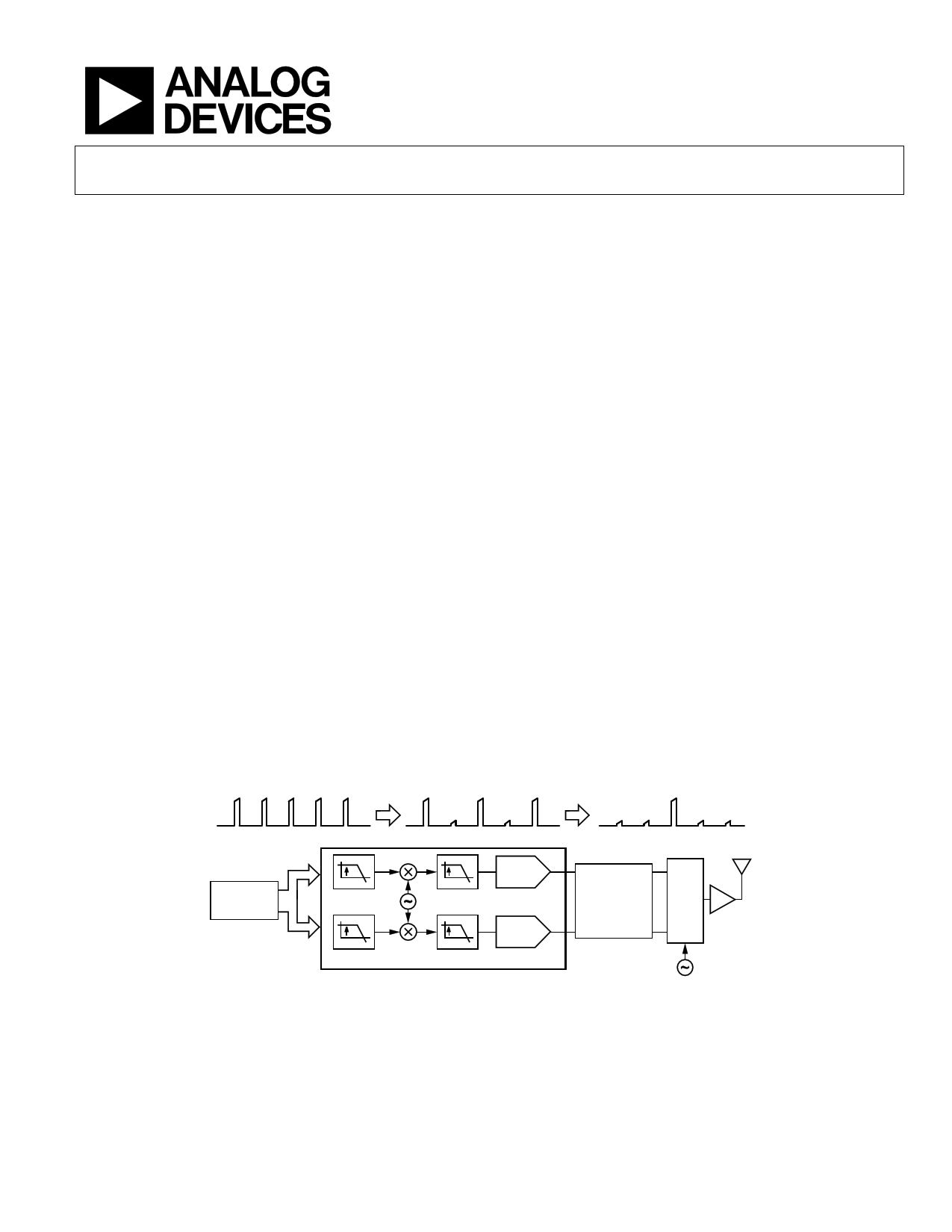
COMPLEX BASEBAND
TYPICAL SIGNAL CHAIN
COMPLEX IF
RF
DC fIF
DIGITAL
BASEBAND
PROCESSOR
2
SIN
COS
2
AD9121
NOTES
1. AQM = ANALOG QUADRATURE MODULATOR.
2/4 I DAC
2/4 Q DAC
Figure 1.
LO – fIF
ANTIALIASING
FILTER
AQM PA
LO
Rev. B
Document Feedback
Information furnished by Analog Devices is believed to be accurate and reliable. However, no
responsibility is assumed by Analog Devices for its use, nor forany infringements of patents orother
rights of third parties that may result from its use. Specifications subjecttochange withoutnotice. No
license is granted by implication or otherwise under any patent or patent rights of Analog Devices.
Trademarks and registered trademarks arethe property of their respectiveowners.
One Technology Way, P.O. Box 9106, Norwood, MA 02062-9106, U.S.A.
Tel: 781.329.4700 ©2012 Analog Devices, Inc. All rights reserved.
Technical Support
www.analog.com
1 page 
AD9121
FUNCTIONAL BLOCK DIAGRAM
Data Sheet
D13P/D13N
D0P/D0N
DCI
FRAME
AD9121
fDATA /2
FIFO PRE
MOD
HB1
NCO
AND
MOD
HB2
HB3
14
14
10 I OFFSET INV
Q OFFSET SINC
14
14
1.2G
DAC 1 AUX
14-BIT
DAC_CLK
1.2G
DAC 2 AUX
14-BIT
IOUT1P
IOUT1N
IOUT2P
IOUT2N
INTERNAL CLOCK TIMING AND CONTROL LOGIC
PROGRAMMING
REGISTERS
SERIAL
INPUT/OUTPUT
PORT
POWER-ON
MULTICHIP
SYNC
RESET SYNCHRONIZATION
10 10
REF
AND
BIAS
DAC CLK_SEL
PLL
CONTROL
0
DAC_CLK
PLL_LOCK
CLOCK
1 MULTIPLIER
(2× TO 16×)
CLK
RCVR
CLK
RCVR
REFIO
FSADJ
DACCLKP
DACCLKN
REFCLKP
REFCLKN
Figure 2.
Rev. B | Page 4 of 60
5 Page 
AD9121
Data Sheet
Pin No.
23
24
25
26
27
28
29
30
31
32
33
34
35
36
37
38
39
40
41
42
43
44
45
46
47
48
49
50
51
52
53
54
55
56
57
58
59
60
61
62
63
64
65
66
67
68
69
70
71
72
Mnemonic
D7P
D7N
D6P
D6N
DCIP
DCIN
DVDD18
DVSS
D5P
D5N
D4P
D4N
D3P
D3N
D2P
D2N
D1P
D1N
D0P
D0N
DVDD18
DVSS
NC/ByteLSBP
NC/ByteLSBN
NC
NC
DVDD18
SDO
SDIO
SCLK
CS
RESET
NC
AVSS
AVDD33
IOUT2P
IOUT2N
AVDD33
AVSS
REFIO
FSADJ
AVSS
AVDD33
IOUT1N
IOUT1P
AVDD33
REFCLKN
REFCLKP
CVDD18
CVDD18
EPAD
Description
Data Bit 7, Positive.
Data Bit 7, Negative.
Data Bit 6, Positive.
Data Bit 6, Negative.
Data Clock Input, Positive.
Data Clock Input, Negative.
1.8 V Digital Supply. Supplies power to digital core and digital data ports.
Digital Common.
Data Bit 5, Positive.
Data Bit 5, Negative.
Data Bit 4, Positive.
Data Bit 4, Negative.
Data Bit 3, Positive.
Data Bit 3, Negative.
Data Bit 2, Positive.
Data Bit 2, Negative.
Data Bit 1, Positive.
Data Bit 1, Negative.
Data Bit 0, Positive.
Data Bit 0, Negative.
1.8 V Digital Supply. Supplies power to digital core and digital data ports.
Digital Common.
This pin is not connected internally (see Figure 3) in word mode. LSB Positive (Data Bit 0) in byte mode.
This pin is not connected internally (see Figure 3) in word mode. LSB Negative (Data Bit 0) in byte mode.
This pin is not connected internally (see Figure 3).
This pin is not connected internally (see Figure 3).
1.8 V Digital Supply. Supplies power to digital core and digital data ports.
Serial Port Data Output (CMOS Levels with Respect to IOVDD).
Serial Port Data Input/Output (CMOS Levels with Respect to IOVDD).
Serial Port Clock Input (CMOS Levels with Respect to IOVDD).
Serial Port Chip Select, Active Low (CMOS Levels with Respect to IOVDD).
Reset, Active Low (CMOS Levels with Respect to IOVDD).
This pin is not connected internally (see Figure 3).
Analog Supply Common.
3.3 V Analog Supply.
Q DAC Positive Current Output.
Q DAC Negative Current Output.
3.3 V Analog Supply.
Analog Supply Common.
Voltage Reference. Nominally 1.2 V output. Should be decoupled to AVSS.
Full-Scale Current Output Adjust. Place a 10 kΩ resistor from this pin to AVSS.
Analog Supply Common.
3.3 V Analog Supply.
I DAC Negative Current Output.
I DAC Positive Current Output.
3.3 V Analog Supply.
PLL Reference Clock Input, Negative. This pin has a secondary function as a synchronization input.
PLL Reference Clock Input, Positive. This pin has a secondary function as a synchronization input.
1.8 V Clock Supply. Supplies clock receivers, clock distribution, and PLL circuitry.
1.8 V Clock Supply. Supplies clock receivers, clock distribution, and PLL circuitry.
The exposed pad (EPAD) must be soldered to the ground plane (AVSS). The EPAD provides an electrical,
thermal, and mechanical connection to the board.
Rev. B | Page 10 of 60
11 Page | ||
| Páginas | Total 30 Páginas | |
| PDF Descargar | [ Datasheet AD9121.PDF ] | |
Hoja de datos destacado
| Número de pieza | Descripción | Fabricantes |
| AD9121 | TxDAC+ Digital-to-Analog Converter | Analog Devices |
| AD9122 | Digital-to-Analog Converter | Analog Devices |
| AD9125 | TxDAC+ Digital-to-Analog Converter | Analog Devices |
| AD9129 | (AD9119 / AD9129) RF Digital-to-Analog Converter | Analog Devices |
| Número de pieza | Descripción | Fabricantes |
| SLA6805M | High Voltage 3 phase Motor Driver IC. |
Sanken |
| SDC1742 | 12- and 14-Bit Hybrid Synchro / Resolver-to-Digital Converters. |
Analog Devices |
|
DataSheet.es es una pagina web que funciona como un repositorio de manuales o hoja de datos de muchos de los productos más populares, |
| DataSheet.es | 2020 | Privacy Policy | Contacto | Buscar |