|
|
|
PDF IDT8T49N203I Data sheet ( Hoja de datos )
| Número de pieza | IDT8T49N203I | |
| Descripción | Universal Frequency Translator | |
| Fabricantes | Integrated Device Technology | |
| Logotipo | ||
Hay una vista previa y un enlace de descarga de IDT8T49N203I (archivo pdf) en la parte inferior de esta página. Total 30 Páginas | ||
|
No Preview Available !
FemtoClock® NG Universal Frequency
Translator
IDT8T49N203I
DATA SHEET
General Description
The IDT8T49N203I is a highly flexible FemtoClock® NG general
purpose, low phase noise Universal Frequency Translator /
Synthesizer with alarm and monitoring functions suitable for
networking and communications applications. It is able to generate
any output frequency in the 0.98MHz - 312.5MHz range and most
output frequencies in the 312.5MHz - 1,300MHz range (see Table 3
for details). A wide range of input reference clocks and a range of
low-cost fundamental mode crystal frequencies may be used as the
source for the output frequency.
The IDT8T49N203I has three operating modes to support a very
broad spectrum of applications:
1) Frequency Synthesizer
• Synthesizes output frequencies from a 16MHz - 40MHz
fundamental mode crystal.
• Fractional feedback division is used, so there are no
requirements for any specific crystal frequency to produce the
desired output frequency with a high degree of accuracy.
2) High-Bandwidth Frequency Translator
• Applications: PCI Express, Computing, General Purpose
• Translates any input clock in the 16MHz - 710MHz frequency
range into any supported output frequency.
• This mode has a high PLL loop bandwidth in order to track input
reference changes, such as Spread-Spectrum Clock
modulation, so it will not attenuate much jitter on the input
reference.
3) Low-Bandwidth Frequency Translator
• Applications: Networking & Communications.
• Translates any input clock in the 8kHz -710MHz frequency
range into any supported output frequency.
• This mode supports PLL loop bandwidths in the 10Hz - 580Hz
range and makes use of an external crystal to provide
significant jitter attenuation.
This device provides two factory-programmed default power-up
configurations burned into One-Time Programmable (OTP) memory.
The configuration to be used is selected by the CONFIG pin. The two
configurations are specified by the customer and are programmed by
IDT during the final test phase from an on-hand stock of blank
devices. The two configurations may be completely independent of
one another.
One usage example might be to install the device on a line card with
two optional daughter cards: an OC-12 option requiring a 622.08MHz
LVDS clock translated from a 19.44MHz input and a Gigabit Ethernet
option requiring a 125MHz LVPECL clock translated from the same
19.44MHz input reference.
To implement other configurations, these power-up default settings
can be overwritten after power-up using the I2C interface and the
device can be completely reconfigured. However, these settings
would have to be re-written next time the device powers-up.
Features
• Fourth generation FemtoClock® NG technology
• Universal Frequency Translator (UFT) / Frequency Synthesizer
• Two outputs, individually programmable as LVPECL or LVDS
• Both outputs may be set to use 2.5V or 3.3V output levels
• Programmable output frequency: 0.98MHz up to 1,300MHz
• Zero ppm frequency translation
• Two differential inputs support the following input types:
LVPECL, LVDS, LVHSTL, HCSL
• Input frequency range: 8kHz - 710MHz
• Crystal input frequency range: 16MHz - 40MHz
• Two factory-set register configurations for power-up default state
• Power-up default configuration pin or register selectable
• Configurations customized via One-Time Programmable ROM
• Settings may be overwritten after power-up via I2C
• I2C Serial interface for register programming
• RMS phase jitter at 155.52MHz, using a 40MHz crystal LVDS
Output (12kHz - 20MHz): 439fs (typical), Low Bandwidth Mode
(FracN)
• RMS phase jitter at 400MHz, using a 40MHz crystal
(12kHz - 40MHz):285fs (typical), Synthesizer Mode (Integer FB)
• Output supply voltage modes:
VCC/VCCA/VCCO
3.3V/3.3V/3.3V
3.3V/3.3V/2.5V (LVPECL only)
2.5V/2.5V/2.5V
• -40°C to 85°C ambient operating temperature
• Available in lead-free (RoHS 6) package
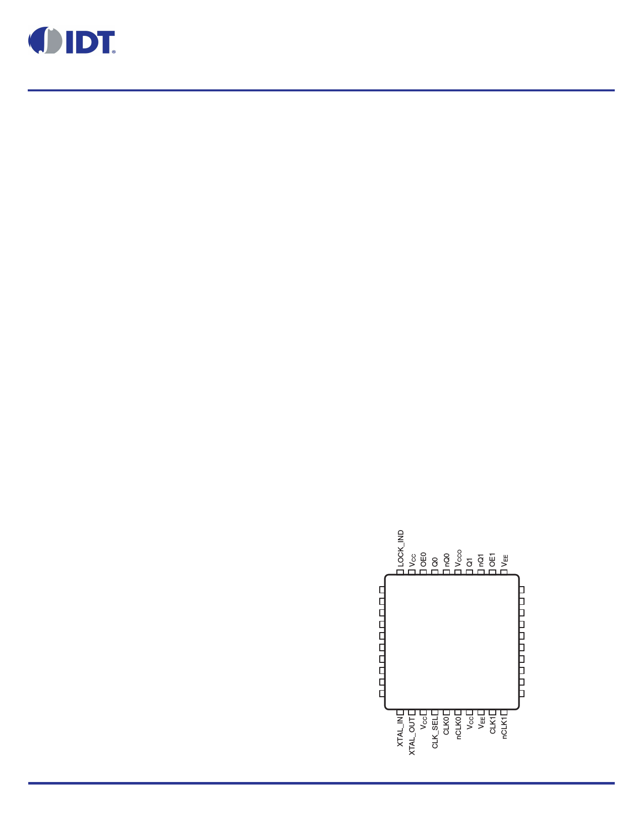
Pin Assignment
CLK_ACTIVE
nc
LF0
LF1
VEE
VCCA
HOLDOVER
CLK0BAD
CLK1BAD
XTALBAD
30 29 28 27 26 25 24 23 22 21
31 20
32 IDT8T49N203I 19
33 18
34 40 Lead VFQFN 17
35 6mm x 6mm x 0.925mm 16
36 K Package 15
37 Top View 14
38 13
39 12
40 11
1 2 3 4 5 6 7 8 9 10
nc
nc
S_A0
S_A1
CONFIG
SCLK
SDATA
VCC
PLL_BYPASS
nc
The Preliminary Information presented herein represents a product in pre-production. The noted characteristics are based on initial product characterization and/or qualification.
Integrated Device Technology, Incorporated (IDT) reserves the right to change any circuitry or specifications without notice
IDT8T49N203ANLGI REVISION C OCTOBER 9, 2012
1
©2012 Integrated Device Technology, Inc.
1 page 
IDT8T49N203I Data Sheet
FemtoClock® NG Universal Frequency Translator
Functional Description
The IDT8T49N203I is designed to provide two copies of almost any
desired output frequency within its operating range (0.98 - 1300MHz)
from any input source in the operating range (8kHz - 710MHz). It is
capable of synthesizing frequencies from a crystal or crystal
oscillator source. The output frequency is generated regardless of
the relationship to the input frequency. The output frequency will be
exactly the required frequency in most cases. In most others, it will
only differ from the desired frequency by a few ppb. IDT configuration
software will indicate the frequency error, if any. The IDT8T49N203I
can translate the desired output frequency from one of two input
clocks. Again, no relationship is required between the input and
output frequencies in order to translate to the output clock rate. In this
frequency translation mode, a low-bandwidth, jitter attenuation option
is available that makes use of an external fixed-frequency crystal or
crystal oscillator to translate from a noisy input source. If the input
clock is known to be fairly clean or if some modulation on the input
needs to be tracked, then the high-bandwidth frequency translation
mode can be used, without the need for the external crystal.
The input clock references and crystal input are monitored
continuously and appropriate alarm outputs are raised both as
register bits and hard-wired pins in the event of any
out-of-specification conditions arising. Clock switching is supported
in manual, revertive & non-revertive modes.
The IDT8T49N203I has two factory-programmed configurations that
may be chosen from as the default operating state after reset. This is
intended to allow the same device to be used in two different
applications without any need for access to the I2C registers. These
defaults may be over-written by I2C register access at any time, but
those over-written settings will be lost on power-down. Please
contact IDT if a specific set of power-up default settings is desired.
Configuration Selection
The IDT8T49N203I comes with two factory-programmed default
configurations. When the device comes out of power-up reset the
selected configuration is loaded into operating registers. The
IDT8T49N203I uses the state of the CONFIG pin or CONFIG register
bit (controlled by the CFG_PIN_REG bit) to determine which
configuration is active. When the output frequency is changed either
via the CONFIG pin or via internal registers, the output behavior may
not be predictable during the register writing and output settling
periods. Devices sensitive to glitches or runt pulses may have to be
reset once reconfiguration is complete.
Once the device is out of reset, the contents of the operating registers
can be modified by write access from the I2C serial port. Users that
have a custom configuration programmed may not require I2C
access.
It is expected that the IDT8T49N203I will be used almost exclusively
in a mode where the selected configuration will be used from device
power-up without any changes during operation. For example, the
device may be designed into a communications line card that
supports different I/O modules such as a standard OC-12 module
running at 622.08MHz or a (255/237) FEC rate OC-12 module
running at 669.32MHz. The different I/O modules would result in a
different level on the CONFIG pin which would select different divider
ratios within the IDT8T49N203I for the two different card
configurations. Access via I2C would not be necessary for operation
using either of the internal configurations.
Operating Modes
The IDT8T49N203I has three operating modes which are set by the
MODE_SEL[1:0] bits. There are two frequency translator modes -
low bandwidth and high bandwidth and a frequency synthesizer
mode. The device will operate in the same mode regardless of which
configuration is active.
Please make use of IDT-provided configuration applications to
determine the best operating settings for the desired configurations
of the device.
Output Dividers & Supported Output Frequencies
In all 3 operating modes, the output stage behaves the same way, but
different operating frequencies can be specified in the two
configurations.
The internal VCO is capable of operating in a range anywhere from
1.995GHz - 2.6GHz. It is necessary to choose an integer multiplier of
the desired output frequency that results in a VCO operating
frequency within that range. The output divider stage N[10:0] is
limited to selection of integers from 2 to 2046. Please refer to Table 3
for the values of N applicable to the desired output frequency.
Table 3. Output Divider Settings & Frequency Ranges
Register
Setting
Nn[10:0]
Frequency
Divider
N
Minimum
fOUT
(MHz)
Maximum
fOUT
(MHz)
0000000000x
2
997.5
1300
00000000010
2
997.5
1300
00000000011
3
665 866.7
00000000100
4
498.75
650
00000000101
5
399
520
0000000011x
6
332.5
433.3
0000000100x
8
249.4
325
0000000101x
10
199.5
260
0000000110x
12
166.3
216.7
0000000111x
14
142.5
185.7
0000001000x
16
124.7
162.5
0000001001x
18
110.8
144.4
...
Even N
1995 / N
2600 / N
1111111111x
2046
0.98
1.27
IDT8T49N203ANLGI REVISION C OCTOBER 9, 2012
5
©2012 Integrated Device Technology, Inc.
5 Page 
IDT8T49N203I Data Sheet
FemtoClock® NG Universal Frequency Translator
ADC_RATE[1:0]
LCK_WIN[1:0]
DBL_XTAL
Sets the ADC sampling rate in Low-Bandwidth Mode as a fraction of the crystal input frequency.
00 = Crystal Frequency / 16
01 = Crystal Frequency / 8
10 = Crystal Frequency / 4 (recommended)
11 = Crystal Frequency / 2
Sets the width of the window in which a new reference edge must fall relative to the feedback edge: 00 = 2usec
(recommended), 01 = 4usec, 10 = 8usec, 11 = 16usec
When set, this bit will double the frequency of the crystal input before applying it to the Phase_Frequency Detector.
Table 4G. Global Status Bits
Register Bits
Function
CLK0BAD
Status Bit for input clock 0. This function is mirrored in the CLK0BAD pin.
0 = input CLK0 is good
1 = input CLK0 is bad. Self clears when input clock returns to good status
CLK1BAD
Status Bit for input clock 1. This function is mirrored in the CLK1BAD pin.
0 = input CLK1 is good
1 = input CLK1 is bad. Self clears when input clock returns to good status
XTALBAD
Status Bit. This function is mirrored on the XTALBAD pin.
0 = crystal input good
1 = crystal input bad. Self-clears when the XTAL clock returns to good status
LOCK_IND
Status bit. This function is mirrored on the LOCK_IND pin.
0 = PLL unlocked
1 = PLL locked
HOLDOVER
Status Bit. This function is mirrored on the HOLDOVER pin.
0 = Input to phase detector is within specifications and device is tracking to it
1 = Phase detector input is not within specifications and DCXO is frozen at last value
CLK_ACTIVE
Status Bit. Indicates which input clock is active. Automatically updates during fail-over switching. Status also
indicated on CLK_ACTIVE pin.
IDT8T49N203ANLGI REVISION C OCTOBER 9, 2012
11
©2012 Integrated Device Technology, Inc.
11 Page | ||
| Páginas | Total 30 Páginas | |
| PDF Descargar | [ Datasheet IDT8T49N203I.PDF ] | |
Hoja de datos destacado
| Número de pieza | Descripción | Fabricantes |
| IDT8T49N203I | Universal Frequency Translator | Integrated Device Technology |
| Número de pieza | Descripción | Fabricantes |
| SLA6805M | High Voltage 3 phase Motor Driver IC. |
Sanken |
| SDC1742 | 12- and 14-Bit Hybrid Synchro / Resolver-to-Digital Converters. |
Analog Devices |
|
DataSheet.es es una pagina web que funciona como un repositorio de manuales o hoja de datos de muchos de los productos más populares, |
| DataSheet.es | 2020 | Privacy Policy | Contacto | Buscar |